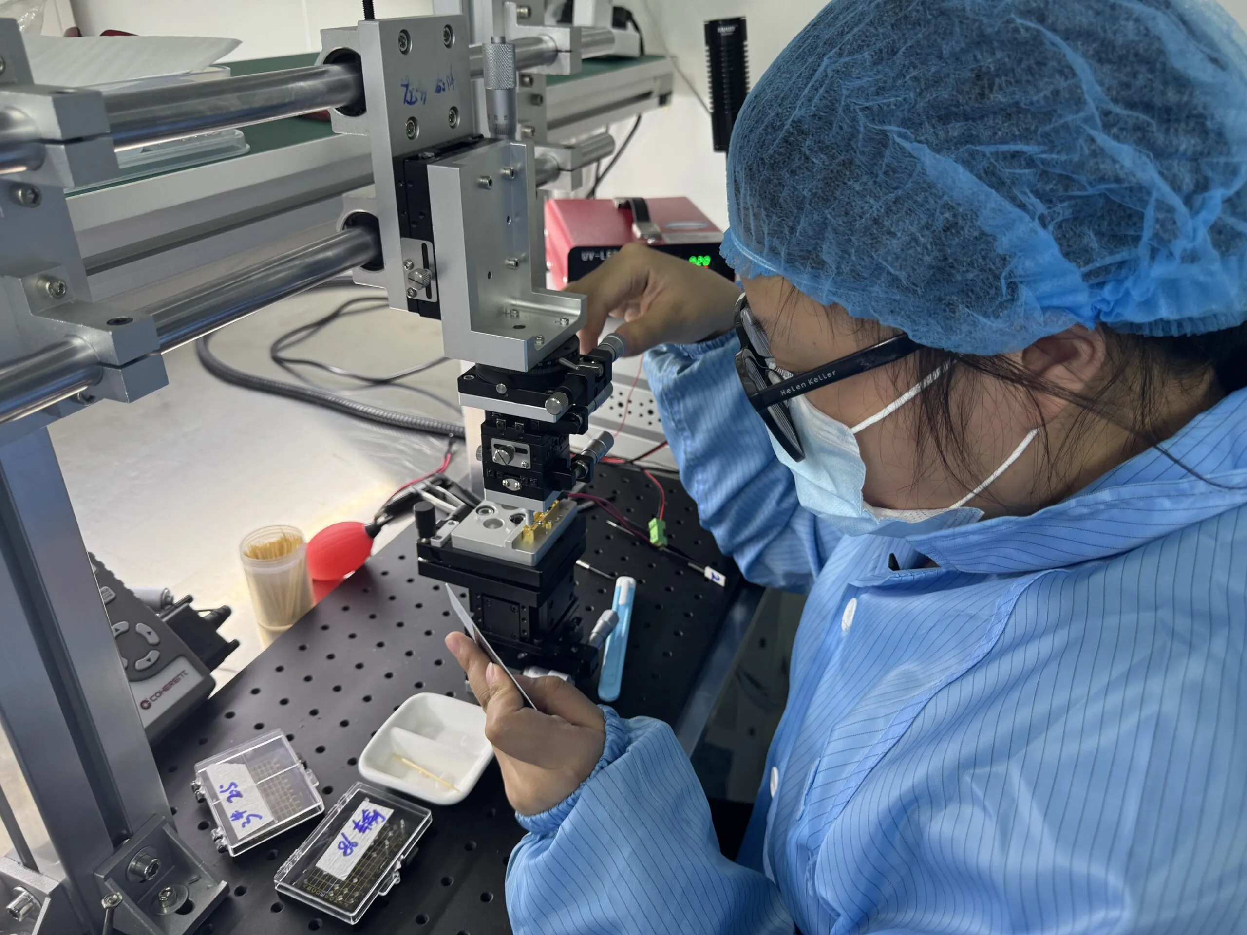
ERDILRF applications
Distance. In your application.
Six civil application areas. Model-specific documentation. A direct path from requirement to evaluation.
Start with the measurement.
A useful distance reading starts with the right module, the right integration and the conditions in front of it.
Explore six civil application areas and a model to evaluate for each. Bring your working distance, object surface, update needs and mechanical constraints to the conversation.
01 / Optical observation
Distance, alongside the image.
For an observation camera or thermal imager, review how the ranging optics fit beside the imaging path. Start with the available space, mounting position and the object you need to measure.
Bring to the review
Optical alignment, the window or enclosure design, object size and surface, and the host connection.
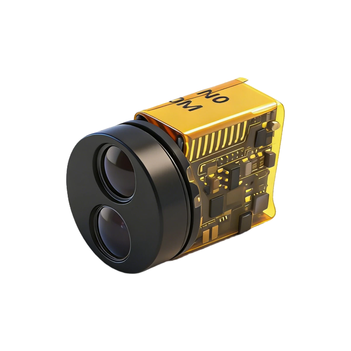 SPD series · UART-TTL
02 / Civil UAVs
Make every integration detail count.
Explore a ranging module for a civil inspection payload by checking the complete installation: payload space, mass allowance, supply and data connection. Evaluate the module against the surfaces and motion expected during the inspection.
Bring to the review
Mounting orientation, vibration, daylight conditions, required updates and the aircraft controller’s handling of unavailable readings.
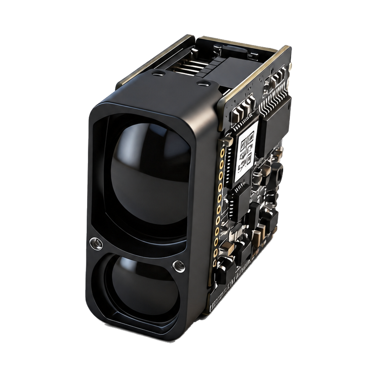 LR E series · UART-TTL
03 / Site monitoring
Plan for the actual surroundings.
For a fixed observation point, begin with the object you need to measure and its position in the scene. Compare published model conditions with your installation before choosing the module and enclosure.
Bring to the review
Object reflectivity, background surfaces, sunlight, weather exposure and the protection required for the complete installation.
LR E series · UART-TTL04 / Industrial sensing
Connect measurement to the controller.
Level monitoring, equipment observation and mobile platforms each bring different surfaces and update requirements. Review the sensor’s electrical interface and output format alongside the mechanical fit.
Bring to the review
Surface and angle, minimum working distance, sampling needs, host data capacity and the response to invalid readings.
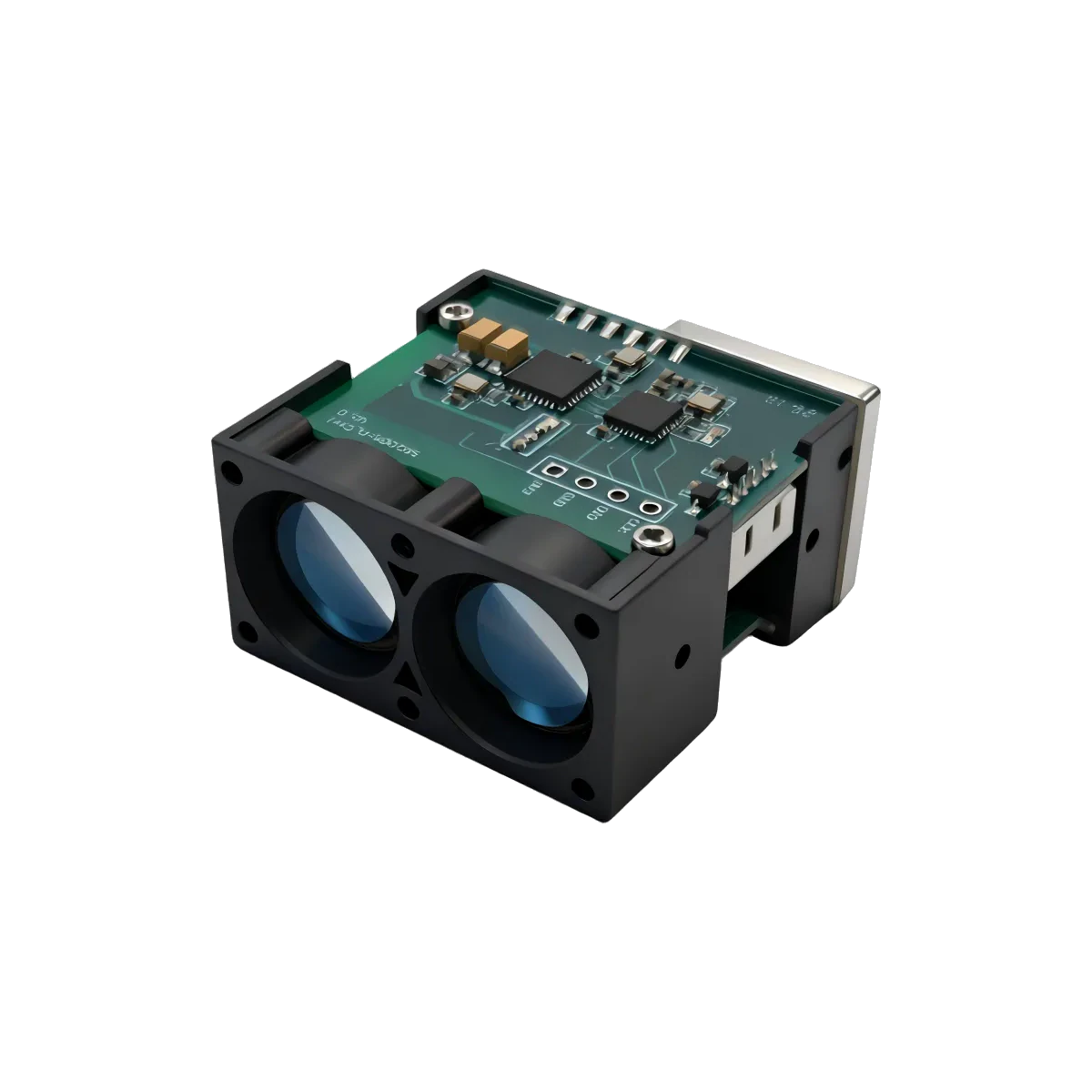 H series · UART / I²C
05 / Handheld instruments
Fit the instrument around the task.
For a portable distance-measurement instrument, start with the housing, optical opening and how the user will take a reading. Review the candidate module’s dimensional drawing before committing to the enclosure.
Bring to the review
Available space, battery and supply design, optical alignment and the required measurement conditions. For LRF1200A1, confirm the separate transmit and reply checksum rules before integration.
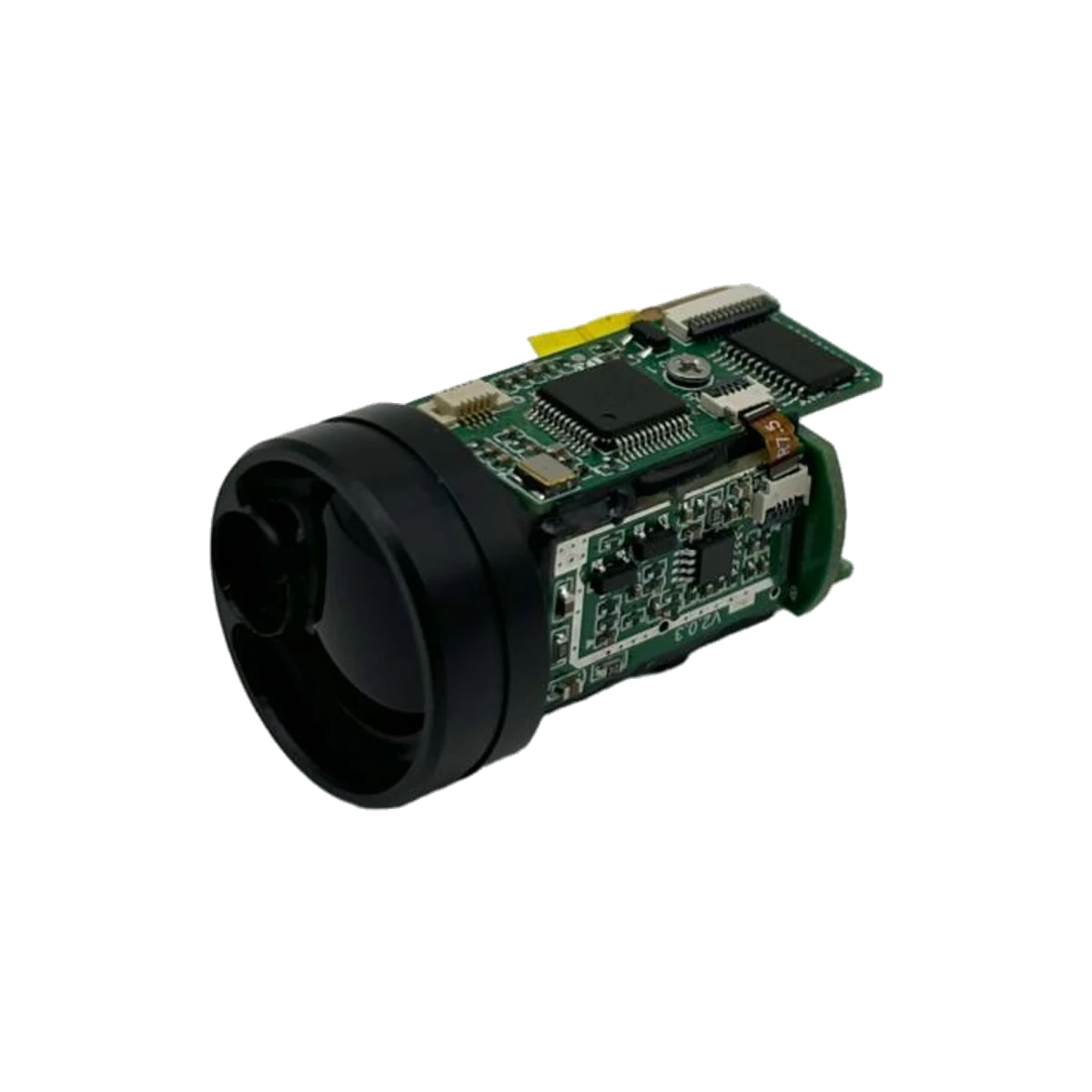 LRF A series · UART, TTL 3.3 V
06 / Field measurement
Define the measurement you need.
Evaluate a distance sensor against the accuracy and working conditions of your field instrument. A headline maximum distance alone does not establish suitability for a survey or mapping workflow.
Bring to the review
Required accuracy, object reflectivity, object size, visibility and alignment. For LRF3000A1, confirm the separate transmit and reply checksum rules before integration.
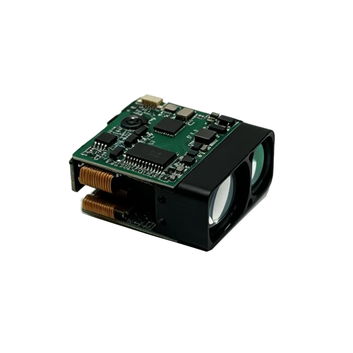 LRF A series · UART, TTL 3.3 V
Bring us the requirement.
Share the distance, object surface, interface, space constraints and quantity. Include a model number if you already have one in mind.
Confirm the current datasheet and laser safety documentation for the specific model and revision. Final suitability depends on your complete device and its operating conditions.