Interface
TTL: Molex 51021-0500; RS-422: J30J.
Discuss integration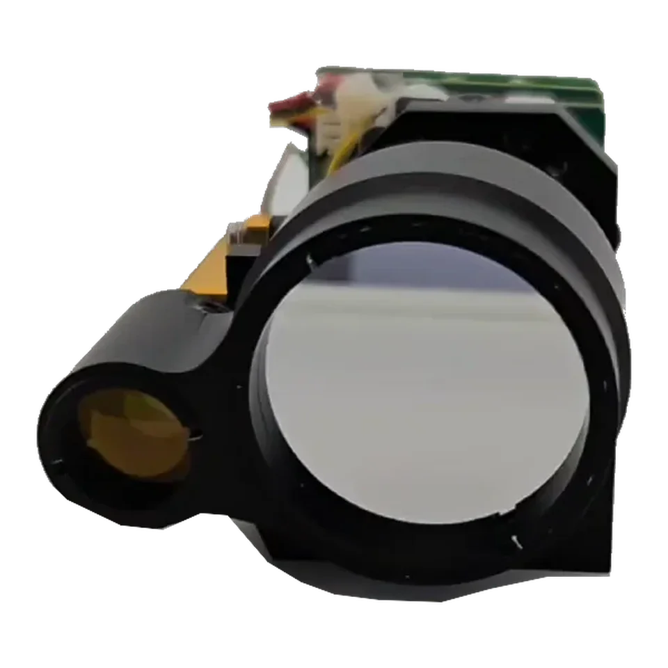
Rangefinders
The ERDI LRF0610C is a 1535 nm laser rangefinder module with 6 km published range, 90 g weight, RS-422/TTL interface, from $1,000 per piece with free worldwide shipping. Specs verified:
1535 nm Laser Rangefinder Module.
Built into your next design.
1 pc $1,000500+ pcs from $700Published unit prices, shipping included · Quantity options
MOQ 1 pc · Free worldwide shipping · Reply within 24 h
Standard warranty: one year
Lead time stated on your PI before payment
Shipped by DHL to customers in the US, India and Ukraine
Published price · shipping included worldwide · pay by card or PayPal, or by bank transfer. Volume price applies automatically.
Added to cart. Go to checkout →
Card or PayPal · Bank transfer · Free worldwide shipping
| Quantity | Unit price | Subtotal at first quantity |
|---|---|---|
| 1–19 | $1,000 | $1,000 |
| 20–100 | $900 | $18,000 |
| 101–299 | $850 | $85,850 |
| 300–499 | $800 | $240,000 |
| 500+ | $700 | $350,000 |
The details
Read every value with its conditions. View the model documents for integration.
| Parameter | Specification & conditions |
|---|---|
| Project | Performance I ndicators |
| Model | LRF0610C |
| Laser Wavelength | 1535±5nm |
| Module laser-safety statement | Class I stated in the module document. Final accessible-emission classification applies to the complete configuration. |
| Divergence Angle | ≤0.5 mrad |
| Laser Energy | ≥200 μJ |
| Launch Lens Diameter | Ø10 mm |
| Receiver Lens Diameter | Ø25 mm |
| Measuring Range (Reflectance 30%; visibility ≥ 8km.) | Reference target(2.3m × 2.3m) ≥6,000m Measuring human target(0.5m × 1.7m) ≥1,500mReflectance 30%; visibility ≥ 8km |
| Minimum Range | ≤15 m |
| Ranging Frequency | 0.5Hz ~10Hz |
| Number of multi-target detections | Up to 3 targets |
| Ranging Accuracy | ±2 m |
| Range Resolution | ≤0.1m |
| Precision Rate | ≥98% |
| False Alarm Rate | ≤1% |
| Connector / interface alternatives | TTL: Molex 51021-0500; RS-422: J30J. |
| Supply Voltage | DC12 V |
| Standby power consumption | ≤1 mW |
| Average power consumption | ≤2.5 W @10 Hz |
| Peak Power Consumption | ≤7 W @12 V |
| Weight | ≤90g |
| Dimension (L×W×H) | 70mm × 32mm × 40mm |
| Operating Temperature | −40~+70 °C |
| Storage Temperature | −55~+75 °C |
| Impact Resistance | Tested to the factory environmental shock test procedure (details on request) |
| Vibration Resistance | Tested to the factory environmental vibration test procedure (details on request) |
| External plug-in XS3 | Model :Molex51021-0500Remark |
| 1 | TTL RX3.3V |
| 2 | TTL TX3.3V |
| 3 | CTRL3.3V-5V power on, 0V power off |
| 4 | +12VPower supply+ |
| 5 | GNDPower supply- |
| Pin | D efinitionFunction |
| 1 | GNDSerial Port Ground |
| 2 | GND12V Input Negative |
| 3 | GND12V Input Negative |
| 4 | VCC 5V12V Input Positive |
| 5 | VCC 5V12V Input Positive |
| 6 | RS422 RX+Serial Port Receive + |
| 7 | RS422 RX-Serial Port Receive - |
| 8 | RS422 TX-Serial Port Transmit - |
| 9 | RS422 TX+Serial Port Transmit + |
Use the current document revision for design review and confirm the ordered connector and mechanical configuration before release.
TTL: Molex 51021-0500; RS-422: J30J.
Discuss integrationDC12 V
Discuss integrationLRF0610C 1535 nm Laser Rangefinder Module
LRF0610C is a laser rangefinder module for OEM integration, with a published test range of 6 km and a RS-422 interface. Confirm target conditions, configuration and the current datasheet before integration.
LRF0610C is a 70 × 32 × 40 mm, ≤90 g 1535 nm rangefinder that reaches ≥6000 m on a reference panel from a 12 V supply, with a choice of TTL or RS-422 output.
WhatsApp about LRF0610CPublished unit prices apply only to the stated quantity band. Configuration, qualification, tax and Incoterm details are confirmed in the quotation.
Integration library
Drawings, test conditions and application notes. Open the part you need.
Reference figures: ≥6000 m on a 2.3 × 2.3 m target and ≥1500 m on a 0.5 × 1.7 m object at 30% reflectance and ≥8 km visibility; accuracy ±2 m; minimum ≤15 m.
LRF0612C gives the same reference-target range in a 65 × 48 × 32 mm, ≤58 g body with a wider 4.5–16 V input but a ≤50 m minimum range. Choose LRF0610C when near-range coverage or RS-422 matters.
Published unit prices start at $700 at 500+ pieces; see Volume Pricing for all quantity bands.
Figures are reproduced from the LRF0610C datasheet. Read each value together with the test condition printed beside it.
LRF0610C is a 1535 nm pulsed distance-measurement module. Its assigned laser source is ER200; receiver-component data below come from the supplied APD-A13B001 R01 document. The three specification levels describe different assemblies and measurement conditions.
| Project | Performance Indicators |
| Model | LRF0610C |
| Laser Wavelength | 1535±5nm |
| Module laser-safety statement | Class I stated in the module document. Final accessible-emission classification applies to the complete configuration. |
|---|---|
| Divergence Angle | ≤0.5 mrad |
| Laser Energy | ≥200 μJ |
| Launch Lens Diameter | Φ10 mm |
| Receiver Lens Diameter | Φ25 mm |
| Measuring Range
(Reflectance 30%; visibility ≥ 8km.) |
Reference target(2.3m×2.3m) ≥6000m
Measuring human target(0.5m×1.7m) ≥1500m |
| Minimum Range | ≤15 m |
| Ranging Frequency | 0.5Hz ~10Hz |
| Number of multi-target detections | Up to 3 targets |
| Ranging Accuracy | ±2 m |
| Range Resolution | ≤0.1m |
| Precision Rate | ≥98% |
| False Alarm Rate | ≤1% |
| Connector / interface alternatives | TTL: Molex 51021-0500; RS-422: J30J. |
| Supply Voltage | DC12 V |
| Standby power consumption | ≤1 mW |
| Average power consumption | ≤2.5 W @10 Hz |
| Peak Power Consumption | ≤7 W @12 V |
| Weight | ≤90g |
| Dimension (L×W×H) | 70mm×32mm×40mm |
| Operating Temperature | -40~+70 ℃ |
| Storage Temperature | -55~+75 ℃ |
| Impact Resistance | Tested to the factory environmental shock test procedure (details on request) |
| Vibration Resistance | Tested to the factory environmental vibration test procedure (details on request) |
|
External plug-in XS3 |
Model:Molex51021-0500 |
Remark |
|
1 |
TTL RX |
3.3V |
|
2 |
TTL TX |
3.3V |
|
3 |
CTRL |
3.3V-5V power on, 0V power off |
|
4 |
+12V |
Power supply+ |
|
5 |
GND |
Power supply- |
|
Pin |
Definition |
Function |
Remarks |
|
1 |
GND |
Serial Port Ground |
|
|
2 |
GND |
12V Input Negative |
|
|
3 |
GND |
12V Input Negative |
|
|
4 |
VCC 5V |
12V Input Positive |
|
|
5 |
VCC 5V |
12V Input Positive |
|
|
6 |
RS422 RX+ |
Serial Port Receive + |
From the upper computer to the rangefinder |
|
7 |
RS422 RX- |
Serial Port Receive - |
From the upper computer to the rangefinder |
|
8 |
RS422 TX- |
Serial Port Transmit - |
From the rangefinder to the upper computer |
|
9 |
RS422 TX+ |
Serial Port Transmit + |
From the rangefinder to the upper computer |
| Parameter | Value |
|---|---|
| Optical wavelength | 1535 nm |
| Pulse energy | 200 µJ (source value; no minimum/maximum qualifier) |
| Optical pulse width | 5 ns (FWHM) |
| Drive pulse width | <2.4 ms |
| Repetition rate | 10 Hz (source operating point, not a stated range) |
| Pulse-energy stability | 10% (definition/statistical method not stated) |
| Raw beam diameter | 0.3 mm |
| Initial beam divergence | 8 mrad (source value; no ≤ qualifier) |
| Transverse mode | TEM00 |
| Operating / storage temperature | −40 to +65 °C / −55 to +85 °C |
| Package dimensions / mass | 21 × 8 × 6.8 mm / 7 g |
| Component electrical entry | 2 V, 10 A |
| Shock / vibration entries | 1500 G, 0.5 ms / 20–2000 Hz, 20 G |
| Stated service life | >1 million shots; test conditions not supplied |
The electrical entries describe the component drive, not the module supply input. Drive conditions and pulse-width definitions must follow the component document and the individual factory record. An optical pulse-width value is not a pump-drive duration.
Small screens: swipe the table horizontally to read all measurement conditions.
| Parameter | Value | Measurement condition / scope |
|---|---|---|
| Device / active diameter | APD-A13B001 R01 / 200 µm | Supplied APD200 document, p1 |
| Detector spectral response interval | 800–1700 nm | Detector response; not the filter passband |
| Responsivity | 0.9 A/W minimum; 1.0 A/W typical | λ = 1550 nm; incident power = 1 µW; M = 1 |
| Dark current | 8 nA typical; 50 nA maximum | VR = VBR − 3 V; incident power = 0 |
| Multiplication factor | M ≥10 / M ≥30 | λ = 1550 nm; 1 µW; respectively VBR − 3 V / VBR − 1 V |
| −3 dB bandwidth | 0.6 GHz minimum; 1.25 GHz typical | M = 10; RL = 50 Ω |
| Breakdown voltage | 35–50 V | Reverse current = 10 µA; incident power = 0 |
| Capacitance | 1.8 pF typical; 2.0 pF maximum | VR = VBR − 3 V; f = 1 MHz |
| Breakdown temperature coefficient | 0.05 minimum / 0.11 typical / 0.15 maximum V/°C | Reverse current = 10 µA; dark; −55 to +85 °C |
| Operating / storage temperature | −40 to +85 °C / −55 to +125 °C | Component absolute-maximum table; not module environmental ratings |
| Maximum bias | VBR | Absolute maximum, not a recommended operating setpoint |
| Maximum forward / reverse current | 5 mA / 3 mA | Absolute maximum ratings, not continuous design targets |
| Filter centre wavelength | 1535 ±5 nm | Supplied filter table, p3 |
| Filter FWHM | <37 nm | Full width at half maximum |
| Transmission at centre wavelength | >90% | Filter specification, not total receiver throughput |
| Blocking specification | T <1%; source lists 400–1750 nm | Stop-band/transition edges are not numerically defined; the stated blocking span is not a guarantee at every wavelength. |
| Optical surface quality | 60/40 | Source label: surface quality; not a transmission value |
Responsivity is measured at 1550 nm; a value measured there is not silently relabeled as a measured 1535 nm value. Absolute maxima are stress limits. The filter document includes an illustrative spectrum, but does not define numerical transition edges or off-axis performance. No additional spectral guarantee is inferred.
For long cables or electrically noisy installations. TTL suits short connections to a nearby controller.
The datasheet gives ≥1500 m on 0.5 × 1.7 m at 30% reflectance.
≤15 m.
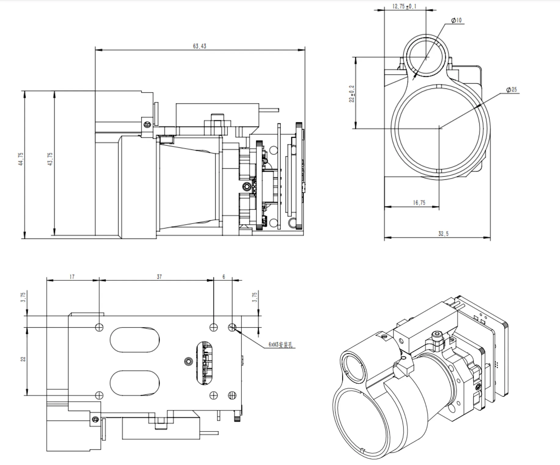
Taken from the LRF0610C outline drawing and user manual. Check hole positions against the drawing or the STEP file before machining a bracket.
Six M3 mounting holes on the bottom face: 22 mm across, with 17 / 37 / 6 mm spacing along the length. Thread depth is not stated on the drawing.
Request the LRF0610C STEP model for your bracket design.
| Pin | Signal | Connection |
|---|---|---|
| 1 | TTL RX | 3.3 V |
| 2 | TTL TX | 3.3 V |
| 3 | CTRL | 3.3 to 5 V = on, 0 V = off |
| 4 | +12 V | power |
| 5 | GND |
| Command | Send (hex) | Reply (hex) | Notes |
|---|---|---|---|
| Single measurement | 55 01 02 00 00 56 | — | |
| Continuous measurement, 1 Hz | 55 02 02 03 E8 BE | — | Data = measurement period in ms (03 E8 = 1000 ms). |
| Stop / standby | 55 00 02 00 00 57 | — | |
| Self-test | 55 03 02 00 00 54 | — | |
| Read ID and versions | 55 EB 02 00 00 BC | — |
Frames follow the LRF0610C user manual; every full frame has been checked against the manual's checksum rule. Open-source drivers: Drivers & wiring.
Engineering Q&A
Answered by ERDI engineers in the community.
Use the integration path that matches your host:
Laser class as stated in the module document. Classification of your finished product depends on its optical path and configuration.
Inspect the model in your browser, or ask for the STEP file for your design review.
Request 3D STEP model — reply within 24 hTechnical inquiry
Share the target, range, interface and expected quantity. Your selected model stays attached to the inquiry.