Mechanical fit
21 × 15 × 7.43 mm
Discuss integration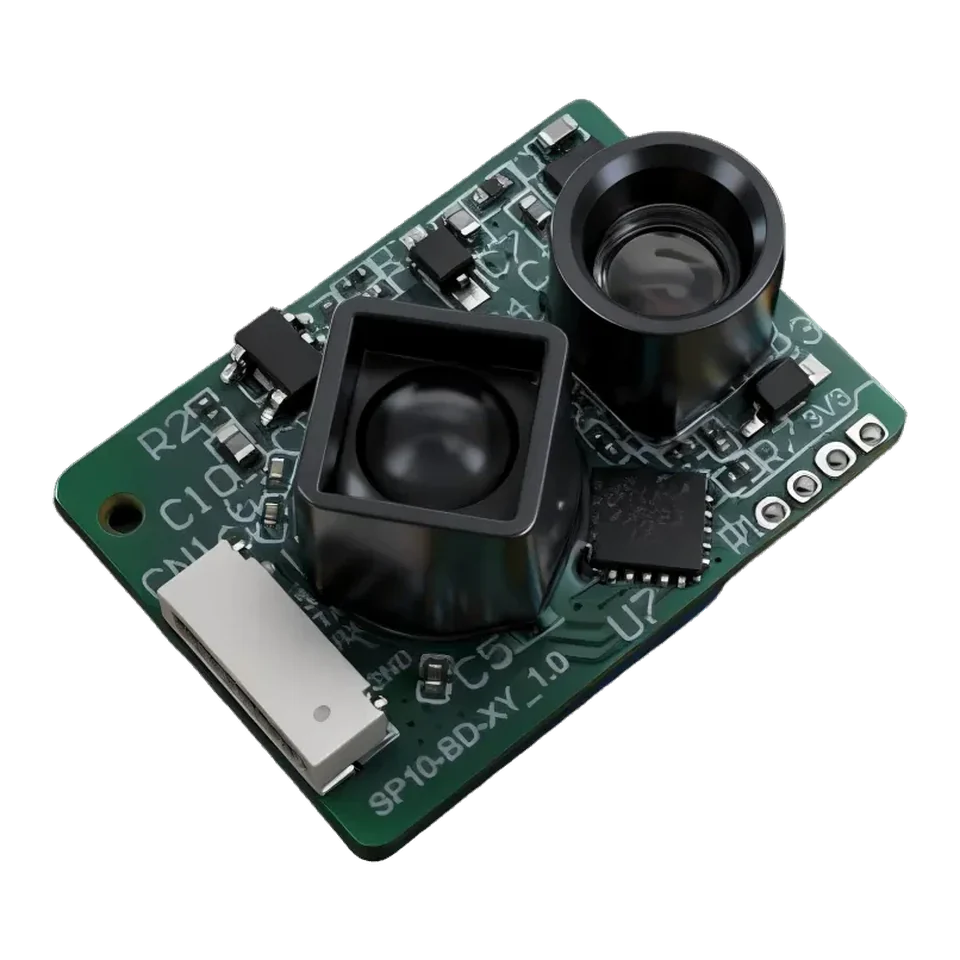
VB series
The ERDI LRF22VB is a 905 nm laser rangefinder module with 20 m published range, 1.5 g weight, UART/I2C interface, from $12 per piece with free worldwide shipping. Specs verified:
905 nm Single-Point LiDAR Sensor.
Built into your next design.
1 pc $121,000+ pcs from $8Published unit prices, shipping included · Quantity options
MOQ 1 pc · Free worldwide shipping · Reply within 24 h
Standard warranty: one year
Lead time stated on your PI before payment
Shipped by DHL to customers in the US, India and Ukraine
Published price · shipping included worldwide · pay by card or PayPal, or by bank transfer. Volume price applies automatically.
Added to cart. Go to checkout →
Card or PayPal · Bank transfer · Free worldwide shipping
| Quantity | Unit price | Subtotal at first quantity |
|---|---|---|
| 1–19 | $12 | $12 |
| 20–30 | $11 | $220 |
| 31–500 | $10 | $310 |
| 501–999 | $9 | $4,509 |
| 1000+ | $8 | $8,000 |
The details
Read every value with its conditions. View the model documents for integration.
| Parameter | Specification & conditions |
|---|---|
| Measurement range | 0.05–20 m (90% reflectivity); 0.05–10 m (10% reflectivity)The two source values remain bound to their stated target reflectivity. |
| Measurement frequency | 200 Hz (alternatives: 100/50/20/10/1 Hz) |
| Accuracy | ±5 cm (<5 m); 1% (≥5 m) |
| Repeatability | ±30 mm |
| Ambient-light immunity | 8 m at 60 klx |
| Reported resolution | 1 mmFront-page feature statement; not an accuracy value |
| Parameter | Specification & conditions |
|---|---|
| Central wavelength | 905 nm |
| Photobiological safety | Class 1 |
| Field of view | 3° |
| Wavelength for indication | N/A |
| Photobiological safety for indication | N/A |
| Parameter | Specification & conditions |
|---|---|
| Supply voltage | 3–3.6 V DC |
| Peak current | 3.3 V at 70 mA |
| Average current | 3.3 V at 40 mA |
| Average power consumption | <0.2 W |
| Communication interface | UART/IIC |
| Parameter | Specification & conditions |
|---|---|
| Protection level | N/A |
| Dimensions | 21 × 15 × 7.43 mm |
| Weight | 1.5 g |
| Operating temperature | −20 °C to +60 °C |
| Wire specification | 6-pin 0.8 mm terminal, HC-0.8-6PWT, with 20 cm tinned stranded wires |
| Customization | Available in appearance / structure / output protocol |
Use the current document revision for design review and confirm the ordered connector and mechanical configuration before release.
21 × 15 × 7.43 mm
Discuss integrationUART/IIC
Discuss integration3–3.6 V DC
Discuss integrationLRF22VB 905 nm Single-Point LiDAR Sensor
LRF22VB is a laser rangefinder module for UAV payloads, with a published test range of 20 m and a UART interface. Confirm target conditions, configuration and the current datasheet before integration.
LRF22VB is a 21 × 15 × 7.43 mm, 1.5 g single-point DToF sensor (905 nm, 0.05–20 m) with up to 200 Hz output, for drone altitude hold and robot or AGV obstacle sensing.
WhatsApp about LRF22VBPublished unit prices apply only to the stated quantity band. Configuration, qualification, tax and Incoterm details are confirmed in the quotation.
Integration library
Drawings, test conditions and application notes. Open the part you need.
Figures are reproduced from the LRF22VB datasheet. Read each value together with the test condition printed beside it.
| Parameter | Value | Source condition |
|---|---|---|
| Measurement range | 0.05-20 m (90% reflectivity); 0.05-10 m (10% reflectivity) | Range differs with target reflectivity. |
| Measurement frequency | 200 Hz (alternatives: 100/50/20/10/1 Hz) | Per model datasheet |
| Accuracy | ±5 cm (<5 m); 1% (≥5 m) | Per model datasheet |
| Repeatability | ±30 mm | Per model datasheet |
| Ambient-light immunity | 8 m at 60 klx | Per model datasheet |
| Reported resolution | 1 mm | Feature claim, not a measured accuracy |
| Parameter | Value | Source condition |
|---|---|---|
| Central wavelength | 905 nm | Per model datasheet |
| Photobiological safety | Class 1 | Per model datasheet |
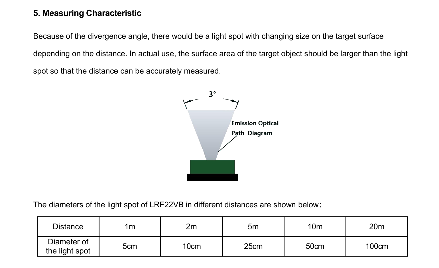
| Field of view | 3° | Per model datasheet |
| Wavelength for indication | N/A | Per model datasheet |
| Photobiological safety for indication | N/A | Per model datasheet |
| Parameter | Value | Source condition |
|---|---|---|
| Supply voltage | 3-3.6 V DC | Per model datasheet |
| Peak current | 3.3 V at 70 mA | Per model datasheet |
| Average current | 3.3 V at 40 mA | Per model datasheet |
| Average power consumption | <0.2 W | Per model datasheet |
| Communication interface | UART/IIC | Per model datasheet |
| Parameter | Value | Source condition |
|---|---|---|
| Protection level | N/A | Per model datasheet |
| Dimensions | 21 × 15 × 7.43 mm | Per model datasheet |
| Weight | 1.5 g | Per model datasheet |
| Operating temperature | -20°C to +60°C | Per model datasheet |
| Wire specification | 6-pin 0.8 mm terminal, HC-0.8-6PWT, with 20 cm tinned stranded wires | Per model datasheet |
| Customization | Housing, structure and output protocol can be customised | Per model datasheet |
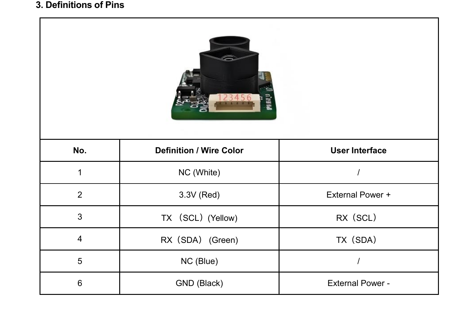
Signal names and directions are transcribed from the model source.
| Pin | Signal | Function |
|---|---|---|
| 1 | NC (white) | Not connected |
| 2 | 3.3V (red) | External power positive |
| 3 | TX / SCL (yellow) | Host RX / SCL |
| 4 | RX / SDA (green) | Host TX / SDA |
| 5 | NC (blue) | Not connected |
| 6 | GND (black) | External power negative |
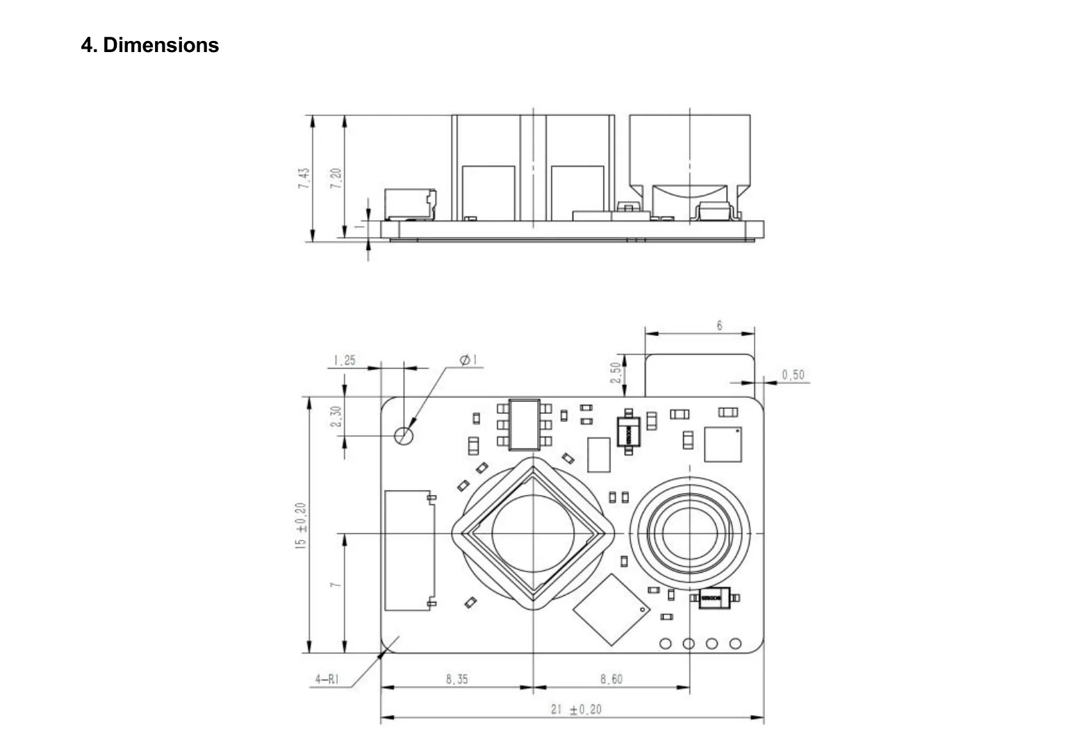
These figures are extracted from the named model source without generative modification.
No, the input is 3–3.6 V.
200 Hz default; 100, 50, 20, 10 and 1 Hz alternatives.
Both are listed.
Taken from the LRF22VB outline drawing and user manual. Check hole positions against the drawing or the STEP file before machining a bracket.
One Ø1 mm hole near the board corner. No thread specification is printed on the drawing.
Request the LRF22VB STEP model for your bracket design.
| Pin | Signal | Wire | Connection |
|---|---|---|---|
| 1 | NC | white | not connected |
| 2 | 3.3 V | red | external power + |
| 3 | TX / SCL | yellow | connect to host RX / SCL |
| 4 | RX / SDA | green | connect to host TX / SDA |
| 5 | NC | blue | not connected |
| 6 | GND | black | external power - |
| Command | Send (hex) | Reply (hex) | Notes |
|---|---|---|---|
| Start measurement | 5A 0A 02 02 00 F1 | 5A 8A 02 02 00 71 | |
| Stop measurement | 5A 0A 02 00 00 F3 | 5A 8A 02 00 00 73 | |
| Read serial number | 5A 0D 04 0D 0D 0D 0D BA | 5A 8D 04 10 01 00 00 5D | Reply 10 01 00 00 = serial number 272 (little-endian). |
| Read firmware version | 5A 16 02 16 16 BB | 5A 96 02 03 02 62 | Reply 03 02 = V2.3. |
| Set baud rate to 115200 | 5A 06 02 80 04 73 | 5A 86 02 80 04 F3 | Little-endian codes: 60 00 = 9600, C0 00 = 19200, 80 01 = 38400, 80 04 = 115200, 00 09 = 230400, 00 0A = 256000, 00 12 = 460800. |
| Set output frequency to 10 Hz | 5A 0B 02 E7 03 08 | 5A 8B 02 E7 03 88 | E7 03 = divisor 999; f = 10,000 / (divisor + 1). |
| Switch to I2C | 5A 1F 02 1F 1F A0 | 5A 9F 02 1F 1F 20 | Reply confirms the switch. |
Frames follow the LRF22VB user manual; every full frame has been checked against the manual's checksum rule. Open-source drivers: Drivers & wiring.
Engineering Q&A
Answered by ERDI engineers in the community.
Use the integration path that matches your host:
Laser class as stated in the module document. Classification of your finished product depends on its optical path and configuration.
Inspect the model in your browser, or ask for the STEP file for your design review.
Request 3D STEP model — reply within 24 hSame series
Open a nearby model to compare range, SWaP and interface choices.
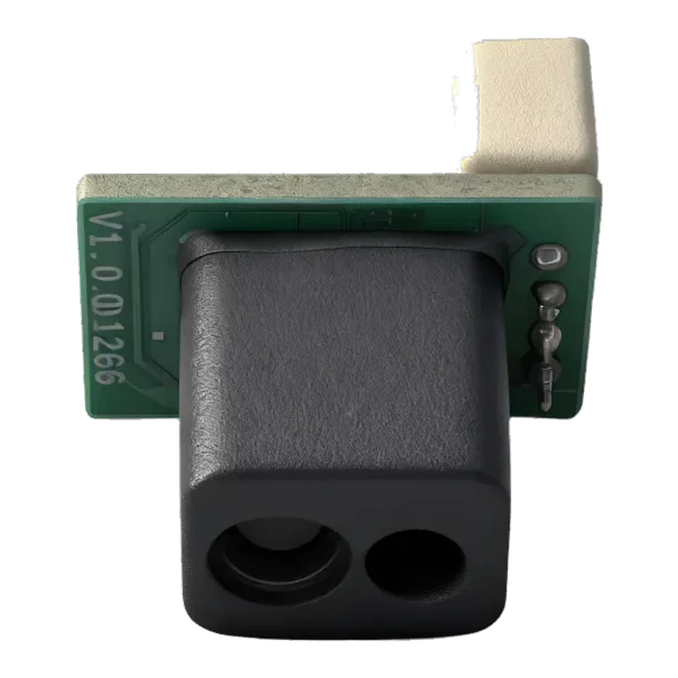
LRF10VB Single-Point 9 m DToF LiDAR Sensor for Camera Focusing, Security Monitoring and Smart Devices
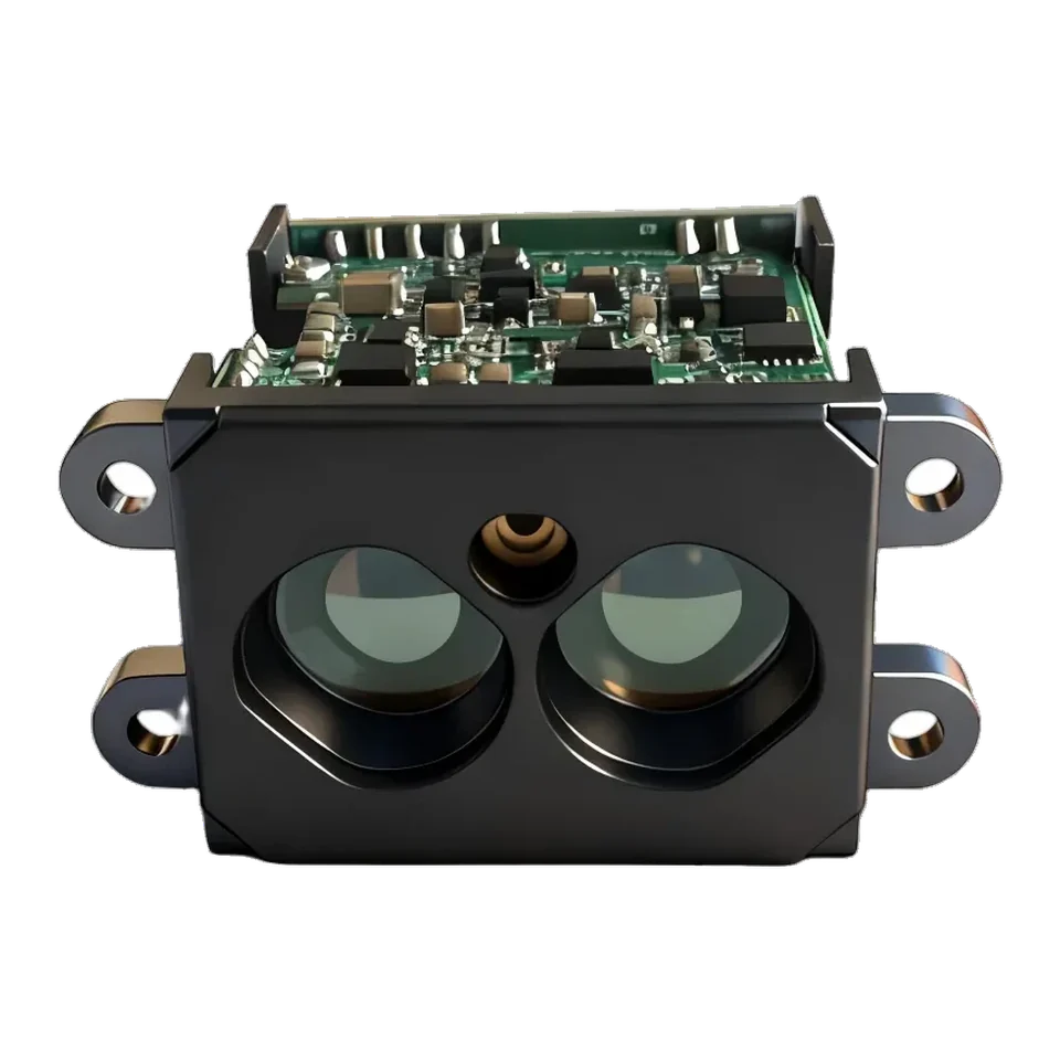
LRF50H High-Speed 50 m LiDAR Distance Sensor for Overhead Cranes, Carriage Distance Control and Industrial Safety
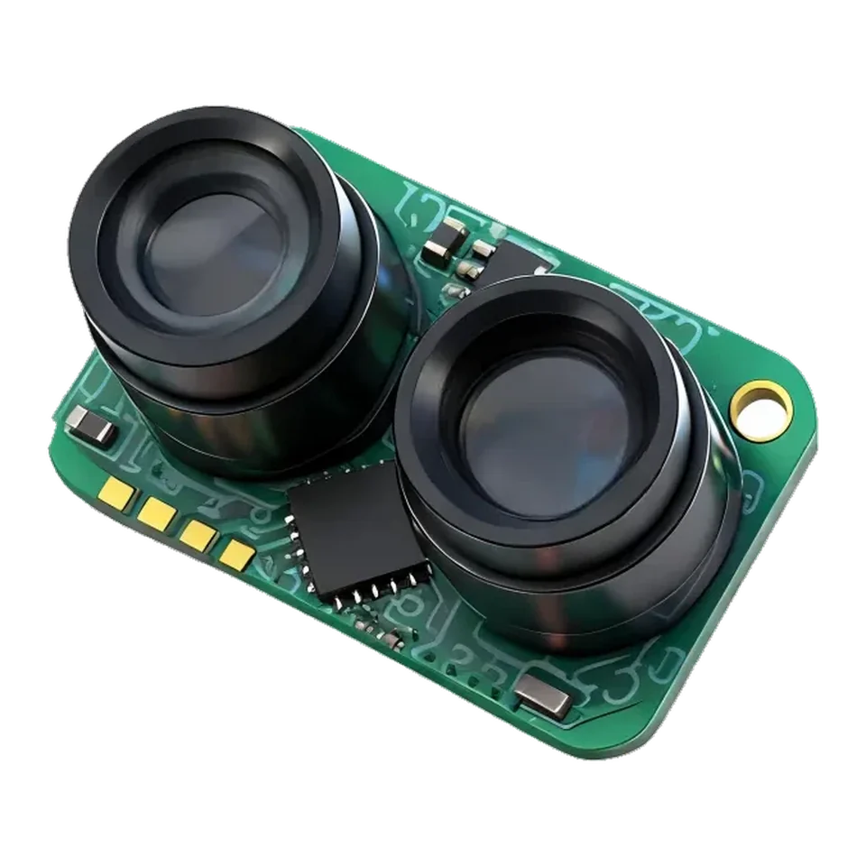
LRF50VB 50m Single-Point DToF LiDAR Sensor for Industrial Automation, AGV and Traffic Safety Monitoring
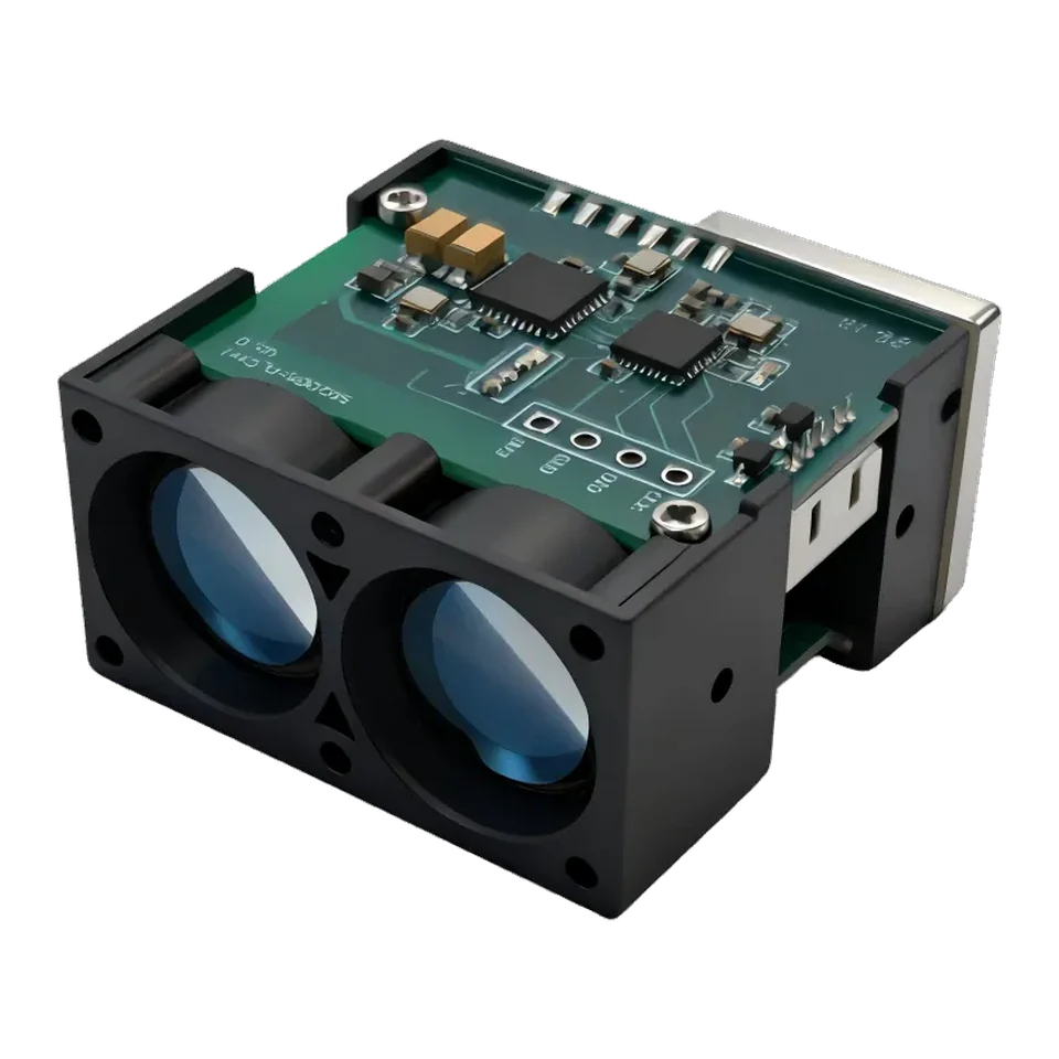
LRF100H 100 m Industrial DToF LiDAR Distance Sensor for Wind Power, Landslide and Level Monitoring
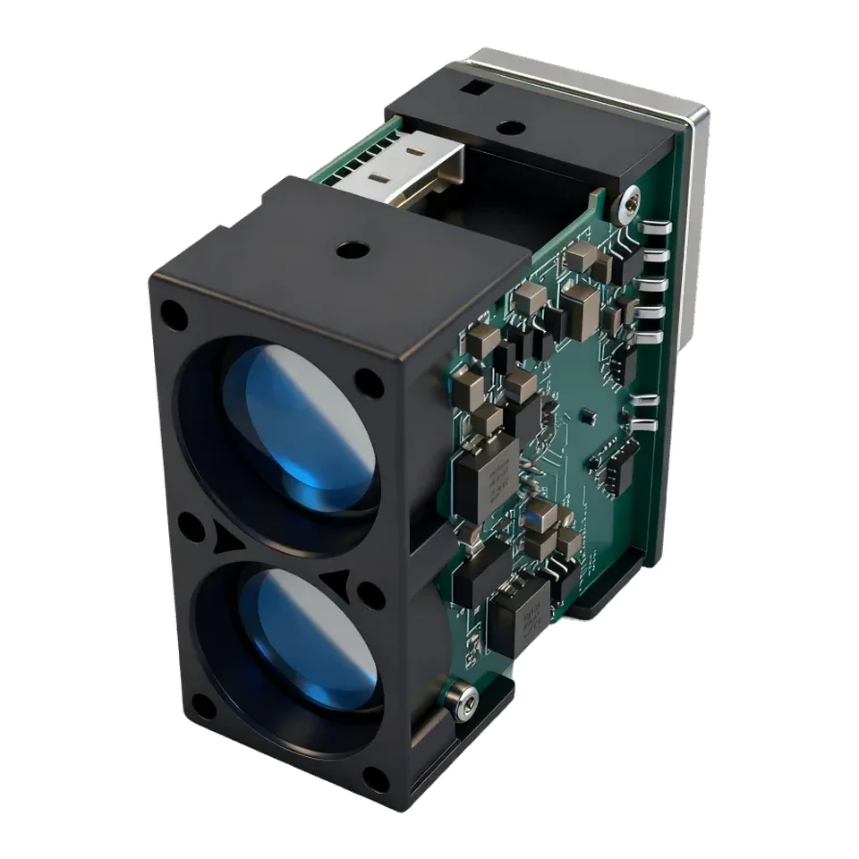
LRF200H 200 m Industrial DToF LiDAR Distance Sensor for Port Cranes, Long Conveyors and Tunnel Safety
Technical inquiry
Share the target, range, interface and expected quantity. Your selected model stays attached to the inquiry.