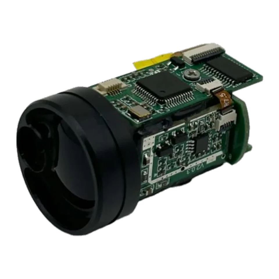
Interface
UART, 3.3 V TTL; customizable (See the controlled model document)
Discuss integration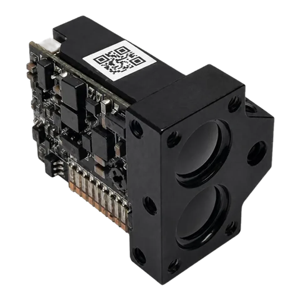
SPD series
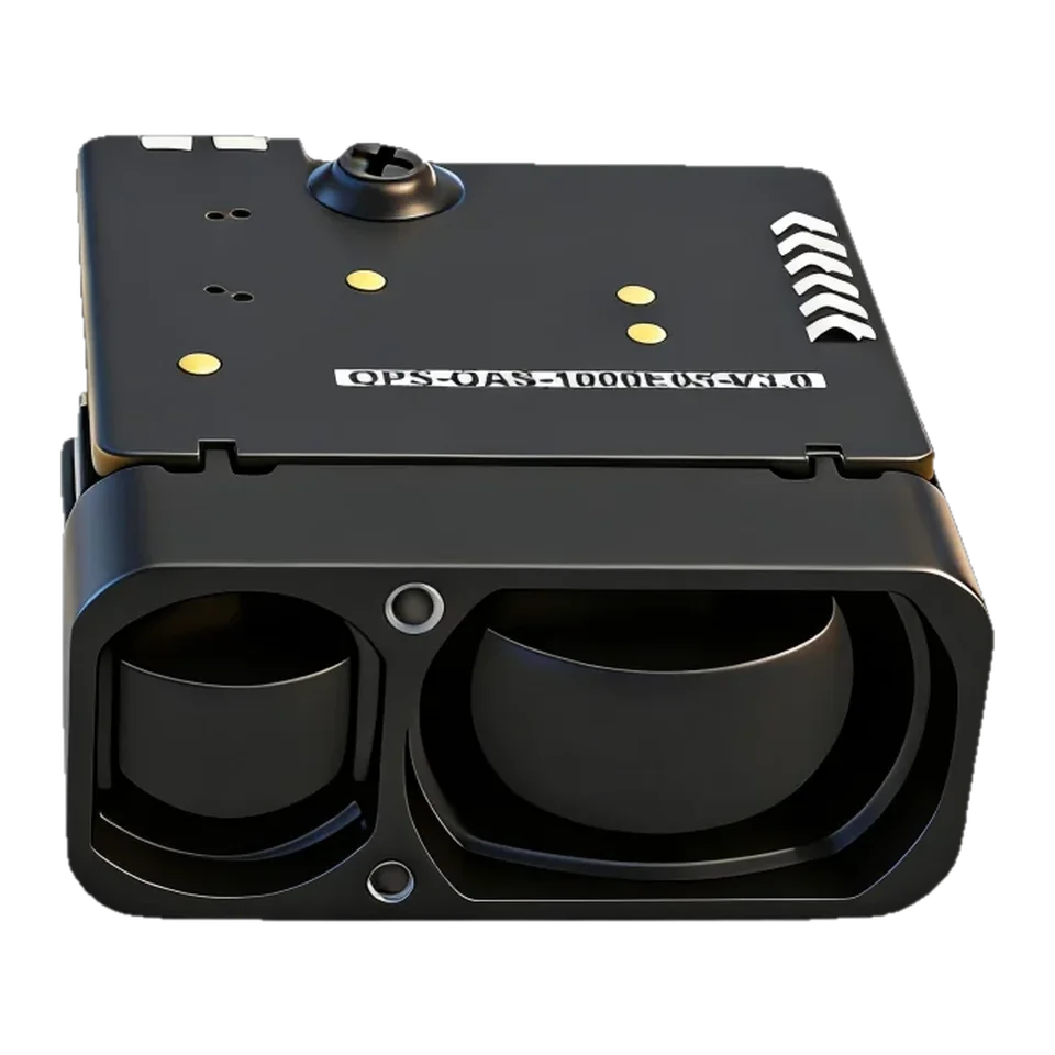
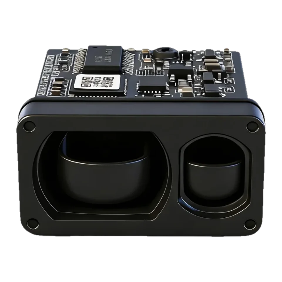
The ERDI SPD1200N3 is a 905 nm laser rangefinder module with 1 km published range, 6 g weight, UART/TTL interface, from $94.50 per piece with free worldwide shipping. Specs verified:
905 nm Laser Rangefinder Module.
Built into your next design.
1 pc $94.50501+ pcs from $36.75Published unit prices, shipping included · Quantity options
MOQ 1 pc · Free worldwide shipping · Reply within 24 h
Standard warranty: one year
Lead time stated on your PI before payment
Shipped by DHL to customers in the US, India and Ukraine
Published price · shipping included worldwide · pay by card or PayPal, or by bank transfer. Volume price applies automatically.
Added to cart. Go to checkout →
Card or PayPal · Bank transfer · Free worldwide shipping
| Quantity | Unit price | Subtotal at first quantity |
|---|---|---|
| 1–30 | $94.50 | $94.50 |
| 31–200 | $73.50 | $2,278.50 |
| 201–500 | $52.50 | $10,552.50 |
| 501+ | $36.75 | $18,411.75 |
The details
Read every value with its conditions. View the model documents for integration.
| Parameter | Specification & conditions |
|---|---|
| Laser wavelength | 905 ± 5 nmRanging emitter; not the indication-laser wavelength |
| Beam divergence | <6 mradSee the controlled model document |
| Optical element | Aspheric lensSee the controlled model document |
| Receive / transmit aperture | Ø6.5 mmSee the controlled model document |
| Measurement range | 3–1,000 mBuilding target; visibility ≥10 km; humidity ≤60% |
| Ranging accuracy | ±0.5 m at d ≤100 m; ±(0.5 m + 0.00075d) for 100 m < d <1,000 md is distance in meters; no additional endpoint accuracy inferred |
| Measurement update rate | 2.5–15 HzVaries with distance; not the laser pulse repetition rate |
| Measurement success rate | ≥98%Source rating; validate representative targets and conditions |
| False alarm rate | ≤1%Source rating; not a universal field guarantee |
| Communication interface | UART, 3.3 V TTL; customizableSee the controlled model document |
| Default baud rate | 115200 bpsSee the controlled model document |
| Supply voltage | DC 3.3–5 VDoes not imply 5 V tolerance on serial inputs |
| Startup time | ≤200 msSee the controlled model document |
| Instantaneous startup current | Approximately 200 mASee the controlled model document |
| Standby power consumption | ≤0.3 WSee the controlled model document |
| Average power consumption | ≤0.5 WSee the controlled model document |
| Operating temperature | −20 to +60 °CSee the controlled model document |
| Storage temperature | −30 to +70 °CSee the controlled model document |
| Ingress protection | IP67 within the lens cavity onlyNot a whole-module or finished-equipment rating |
| Laser safety class | IEC Class 1 stated in the ranging specificationDo not extend this rating to indication/alignment modes or the finished system without confirmation |
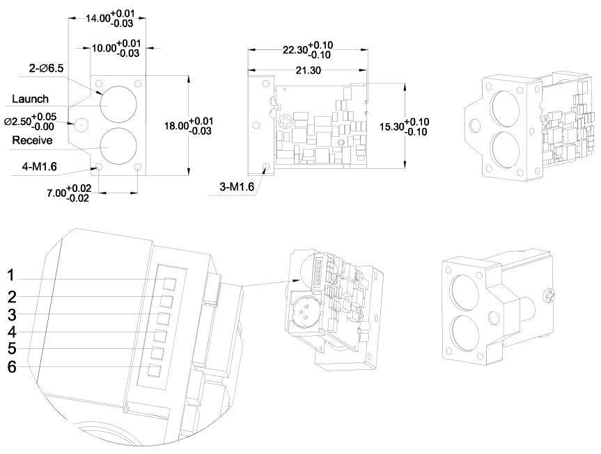
| Nominal body dimensions / material | 14 × 18 × 22.3 mm; rectangular; 6061 aluminum alloyUse the current mechanical drawing and tolerances |
| Weight | ≤6 gSee the controlled model document |
Use the current document revision for design review and confirm the ordered connector and mechanical configuration before release.
UART, 3.3 V TTL; customizable (See the controlled model document)
Discuss integrationDC 3.3–5 V (Does not imply 5 V tolerance on serial inputs)
Discuss integrationSPD1200N3 905 nm Laser Rangefinder Module
SPD1200N3 is a laser rangefinder module for OEM integration, with a published test range of 1 km and a UART interface. Confirm target conditions, configuration and the current datasheet before integration.
SPD1200N3 is a 14 × 18 × 22.3 mm, ≤6 g single-photon 905 nm rangefinder with a built-in indication laser, for devices where the user needs to see where the module is aiming.
WhatsApp about SPD1200N3Published unit prices apply only to the stated quantity band. Configuration, qualification, tax and Incoterm details are confirmed in the quotation.
Integration library
Drawings, test conditions and application notes. Open the part you need.
Figures are reproduced from the SPD1200N3 datasheet. Read each value together with the test condition printed beside it.
| Parameter | Value | Source condition |
|---|---|---|
| Laser wavelength | 905 ± 5 nm | Ranging emitter; not the indication-laser wavelength |
| Beam divergence | <6 mrad | See the controlled model document |
| Optical element | Aspheric lens | See the controlled model document |
| Receive / transmit aperture | Ø6.5 mm | See the controlled model document |
| Measurement range | 3–1000 m | Building target; visibility ≥10 km; humidity ≤60% |
| Ranging accuracy | ±0.5 m at d ≤100 m; ±(0.5 m + 0.00075d) for 100 m < d <1000 m | d is distance in meters; no additional endpoint accuracy inferred |
| Measurement update rate | 2.5–15 Hz | Varies with distance; not the laser pulse repetition rate |
| Measurement success rate | ≥98% | Source rating; validate representative targets and conditions |
| False alarm rate | ≤1% | Source rating; not a universal field guarantee |
| Communication interface | UART, 3.3 V TTL; customizable | See the controlled model document |
| Default baud rate | 115200 bps | See the controlled model document |
| Supply voltage | DC 3.3–5 V | Does not imply 5 V tolerance on serial inputs |
| Startup time | ≤200 ms | See the controlled model document |
| Instantaneous startup current | Approximately 200 mA | See the controlled model document |
| Standby power consumption | ≤0.3 W | See the controlled model document |
| Average power consumption | ≤0.5 W | See the controlled model document |
| Operating temperature | −20 to +60 °C | See the controlled model document |
| Storage temperature | −30 to +70 °C | See the controlled model document |
| Ingress protection | IP67 within the lens cavity only | Not a whole-module or finished-equipment rating |
| Laser safety class | IEC Class 1 stated in the ranging specification | Do not extend this rating to indication/alignment modes or the finished system without confirmation |
| Nominal body dimensions / material | 14 × 18 × 22.3 mm; rectangular; 6061 aluminum alloy | Use the current mechanical drawing and tolerances |
| Weight | ≤6 g | See the controlled model document |
| Pin | Signal | Function |
|---|---|---|
| 1 | GND | Power-supply ground |
| 2 | VCC | Positive supply input |
| 3 | IO (reserved) | Reserved for expansion |
| 4 | TXD | Signal output: module to host |
| 5 | RXD | Signal input: host to module |
| 6 | SW-SHOT | Function enable, active high (>1.2 V); confirm supplied configuration before wiring |
Check the numbered connector view before wiring. Supply voltage and UART input tolerance are different electrical limits.
The model PDF controls product claims. Independent literature explains general principles and does not qualify this module.
No. Use 3.3 V levels even when the module is powered from 5 V.
No, it is stated for the ranging specification only.
3–1000 m with ≥10 km visibility and ≤60% humidity.
Taken from the SPD1200N3 outline drawing and user manual. Check hole positions against the drawing or the STEP file before machining a bracket.
Four M1.6 threaded holes on the front plate (the lower two are 7.00 mm apart), plus three M1.6 holes on the flange side. Thread depth is not stated on the drawing.
Request the SPD1200N3 STEP model for your bracket design.
| Command | Send (hex) | Reply (hex) | Notes |
|---|---|---|---|
| Single measurement | 55 AA 88 FF FF FF FF 84 | 55 AA 88 STA FF DIS_H DIS_L SUM[1:7] | STA = 1: success. DIS_H/DIS_L = distance high/low byte; the reported value is 10 x the measured value. |
| Continuous measurement | 55 AA 89 FF FF FF FF 85 | 55 AA 89 STA FF DIS_H DIS_L SUM[1:7] | STA = 1: success. DIS_H/DIS_L = distance high/low byte; the reported value is 10 x the measured value. |
| Stop measurement | 55 AA 8E FF FF FF FF 8A | 55 AA 8E STA FF FF FF SUM[1:7] | STA = 1: stopped; STA = 0: failed. |
Frames follow the SPD1200N3 user manual; every full frame has been checked against the manual's checksum rule. Open-source drivers: Drivers & wiring.
Engineering Q&A
Answered by ERDI engineers in the community.
Use the integration path that matches your host:
Laser class as stated in the module document. Classification of your finished product depends on its optical path and configuration.
Inspect the model in your browser, or ask for the STEP file for your design review.
Request 3D STEP model — reply within 24 hSame series
Open a nearby model to compare range, SWaP and interface choices.
Technical inquiry
Share the target, range, interface and expected quantity. Your selected model stays attached to the inquiry.