
Application evaluation
Industrial sensing
1 kHz default, 9–36 V in, 0.7 W out.
One beam, one number, no point cloud to process.
Industrial and robotics ranging is not a smaller version of long-range ranging. The distances are centimeters to a few hundred meters, the update rate has to keep up with a control loop, the power budget is often a battery, and — the part that decides the architecture — you usually already know which direction to point.
That is the case for a single-point sensor rather than a scanner. A scanning LiDAR builds a point cloud you then have to process; a fixed-axis DToF module returns one calibrated distance along one known axis, with no mechanical or MEMS assembly in it and no cloud to consume compute. For a drop-off sensor under an AGV, a clearance sensor on an end-effector, a bumper-mounted forward sensor or a height check on a conveyor, that is not a compromise — it is the correct instrument. It also belongs in a fusion stack next to encoders, an IMU and a camera, contributing the one measurement none of those produce cleanly.
LRF100H is the middle of the H-series: 0.05–100 m at 90% reflectivity and 0.05–30 m at 10%, ±10 cm below 10 m and 1% of reading above it, repeatability ±5 cm below 10 m and ±10 cm at 100 m, 20 Hz to 10 kHz with a 1 kHz default, UART or I²C, 9–36 V DC, 100 kLux ambient-light immunity, ≈ 4 mrad field of view, 33 × 34 × 18 mm at 20 ± 2 g, 0.7 W average from 30 mA average / 100 mA peak, terminated in 1.25 mm 5-pin, 50 cm stranded leads.
The 9–36 V input is the detail that usually decides the choice. It matches a control cabinet or a larger AGV chassis rail, which rarely delivers a clean 3.3 V or 5 V at the sensor mounting point. If you are integrating at board level inside a small AMR, the VB-series is the other end of that trade: LRF50VB is 0.05–50 m at 90% / 0.05–20 m at 10%, ±5 cm below 5 m then 1%, a fixed 100 Hz, 3.3–5 V DC, 0.2 W, and 1.3 g in an 18.7 × 11.8 × 13.3 mm body. Wiring a 9–36 V part into a 5 V rail, or a 3.3 V part into an unregulated 24 V supply, is a design error the datasheet catches before the sensor does.
Three things to plan for before you commit a design.
Bus. Everything here is UART-TTL or I²C. No model offers RS-485, RS-232 or CAN natively. If the PLC or the fleet controller expects one of those, budget a converter in the BOM now. And although LRF100H’s table lists I²C, its published protocol does not state an I²C address — ask us rather than borrowing another model’s.
Protection. No H-series spec table carries a protection-rating row at all. For wash-down, outdoor or dusty installations, get the rating in writing for your model before you design the enclosure.
Reflectivity. Size against the worst material in your process, not the best. LRF100H reads 100 m against a 90% surface and 30 m against a 10% one; dark aggregate, powders and matte black fixtures sit at the low end.
Laser class reads Class 1, from the model manual. Appearance, structure and output protocol are listed as customizable on this series.
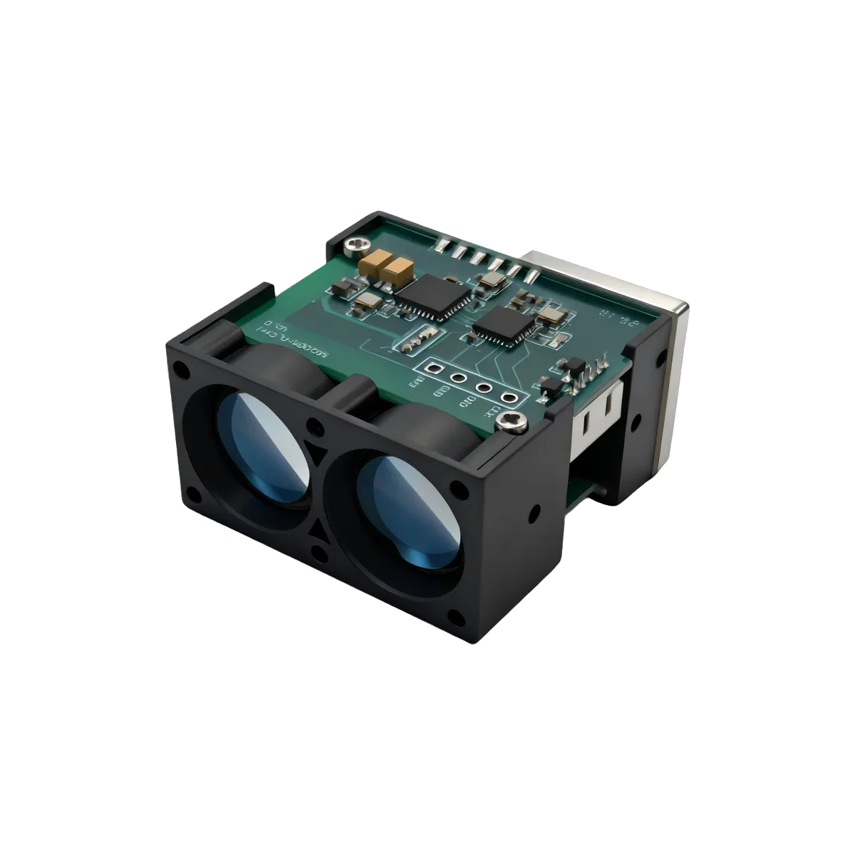
Five H-series modules share one 33 × 34 × 18 mm body.
Bring the measurement conditions and integration constraints into the same review.
01One enclosure, five reaches+
LRF100H, LRF200H, LRF300H, LRF600H and LRF1500H share the same 33 × 34 × 18 mm body at 20 ± 2 g, so moving from 100 m to 1,500 m is a drop-in swap inside your own housing. LRF50H is not in that group — it is 38 × 20 × 30 mm at 15 ± 2 g.
02Repeatability, not accuracy, is the control-loop number+
All the H-series parts quote the same ±10 cm / 1% accuracy, so accuracy tells you nothing about which one behaves better at its own limit. Repeatability does: ±10 cm at the top of LRF100H, ±50 cm at the top of LRF600H, ±100 cm at the top of LRF1500H. Quote the repeatability figure in a stop-distance specification.
03Frame width changes at 1,500 m+
If you plan to reuse one parser across the series: the shorter H-series parts return a 2-byte distance field, and LRF1500H returns a 3-byte field in a wider frame. A reader written against a 600 m module will silently mis-frame every packet from the 1,500 m one. Branch on the model at configuration time.
From the module to the host.
H series · UART / I²C
UART or I²C — and the I²C address is not published.
Check the supply, signal levels, pinout and output format for the exact model and revision. Request any missing detail before connecting your hardware.
LRF100HRelated application pages
Share the model and distance for a technical review.
Share the distance, object surface, interface, space constraints and quantity. Include a model number if you already have one in mind.
Laser distance sensor checklist: level and AGV sensing · Using a 905 nm rangefinder module for AGV/AMR obstacle avoidance · Rangefinder update rate for moving platforms · Python and Arduino, open source, no SDK to license
Confirm the current datasheet and laser safety documentation for the specific model and revision. Final suitability depends on your complete device and its operating conditions.