Performance envelope
Measurement range: 0.05-200 m (90% reflectivity); 0.05-70 m (10% reflectivity) · Accuracy: ±10 cm (<10 m); 1% (≥10 m)
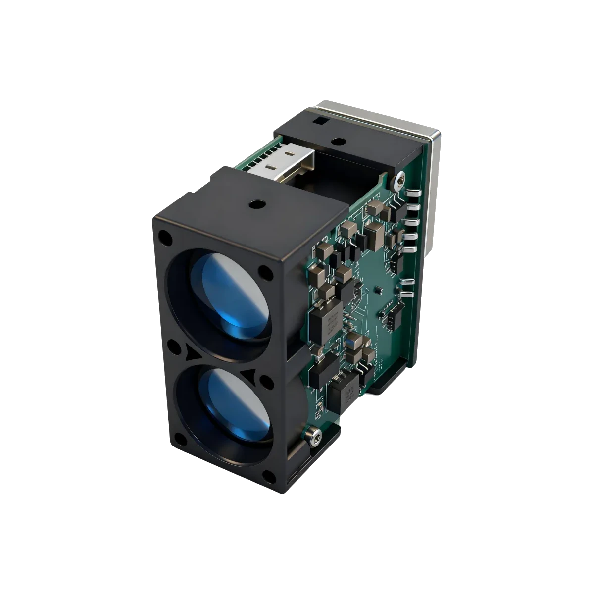
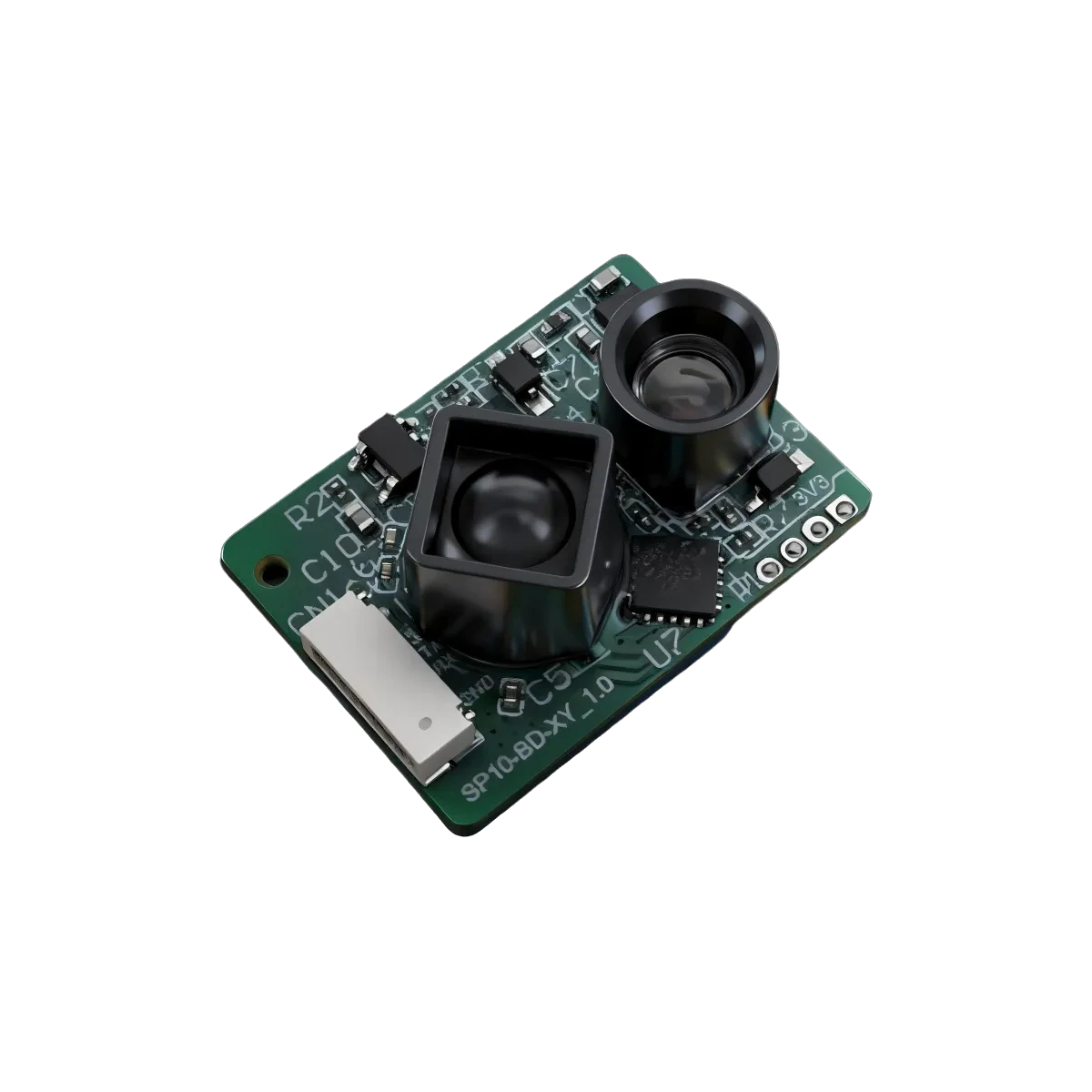
Authentic product views from the ERDI product record. Use the controlled mechanical drawing and connector definition for design release.
Open dedicated 3D viewerOEM laser ranging and photonics module
Product model LRF200H
LRF200H is a 905 nm direct time-of-flight module specified for 0.05-200 m at 90% reflectivity and 0.05-70 m at 10% reflectivity. Its source document specifies 20 Hz-10 kHz operation with 1 kHz default, UART/IIC communication and a 9-36 V DC input.
Use the current controlled document revision for design review and confirm the ordered connector and mechanical configuration before release.
Published unit prices apply only to the stated quantity band. Configuration, qualification, tax and Incoterm details are confirmed in the quotation.
Every value below is bound to the model source named on this page. Qualifiers and test conditions are retained; missing values are not inferred.
| Parameter | Value | Source condition |
|---|---|---|
| Measurement range | 0.05-200 m (90% reflectivity); 0.05-70 m (10% reflectivity) | The two source values remain bound to their stated target reflectivity. |
| Measurement frequency | 20 Hz-10 kHz (default: 1 kHz) | Confirm against the controlled model document |
| Accuracy | ±10 cm (<10 m); 1% (≥10 m) | Confirm against the controlled model document |
| Repeatability | ±5 cm (<10 m); ±10 cm at 200 m | Confirm against the controlled model document |
| Ambient-light immunity | 100 klx | Confirm against the controlled model document |
| Parameter | Value | Source condition |
|---|---|---|
| Central wavelength | 905 nm | Confirm against the controlled model document |
| Photobiological safety | Class 1 | Confirm against the controlled model document |
| Field of view | About 4 mrad | Confirm against the controlled model document |
| Wavelength for indication | N/A | Confirm against the controlled model document |
| Photobiological safety for indication | N/A | Confirm against the controlled model document |
| Parameter | Value | Source condition |
|---|---|---|
| Supply voltage | 9-36 V DC | Confirm against the controlled model document |
| Peak current | 100 mA | Confirm against the controlled model document |
| Average current | 30 mA | Confirm against the controlled model document |
| Average power consumption | 0.7 W | Confirm against the controlled model document |
| Communication interface | UART, IIC | Confirm against the controlled model document |
| Parameter | Value | Source condition |
|---|---|---|
| Protection level | N/A | Confirm against the controlled model document |
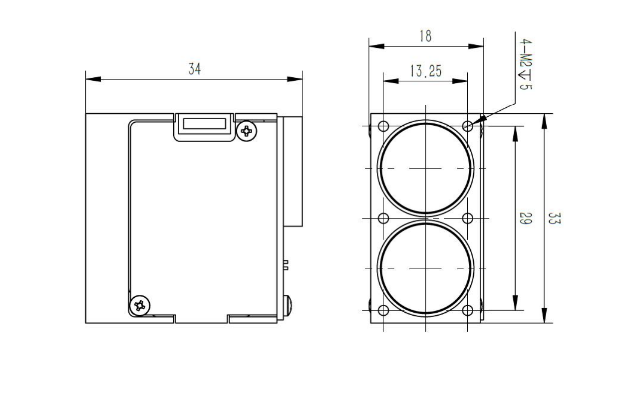
| Dimensions | 33 × 34 × 18 mm | Confirm against the controlled model document |
| Weight | 20 ± 2 g | Confirm against the controlled model document |
| Operating temperature | -20°C to +60°C | Confirm against the controlled model document |
| Wire specification | 1.25 mm, 5P, 50 cm stranded wires | Confirm against the controlled model document |
| Customization | Available in appearance / structure / output protocol | Confirm against the controlled model document |
The source explicitly states support for both single-shot and continuous ranging modes.
The source states integration into real-time data-acquisition systems through standard interfaces such as UART.
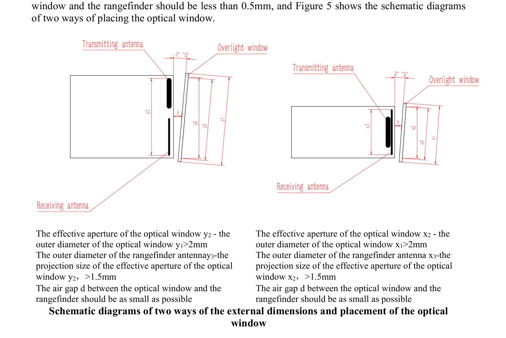
The optical-window guidance recommends H-K9L glass, a wedge-angle tolerance of no more than 3 arcminutes, and an 855-955 nm anti-reflection coating with source-stated transmittance of at least 99.5%.
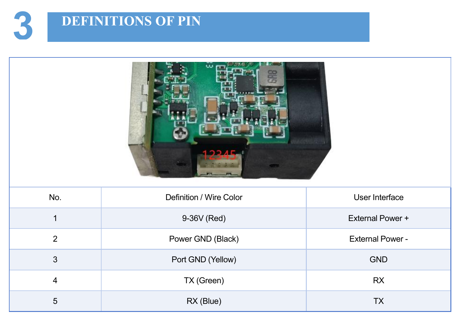
Signal names and directions are transcribed from the model source.
| Pin | Signal | Source-stated function |
|---|---|---|
| 1 | 9-36V (red) | External power positive |
| 2 | Power GND (black) | External power negative |
| 3 | Port GND (yellow) | GND |
| 4 | TX (green) | Host RX |
| 5 | RX (blue) | Host TX |
These figures are extracted from the named model source without generative modification.
The LRF200H model document identifies the product as direct time of flight (DToF). It determines distance from the delay between an emitted optical pulse and the accepted return.
Real performance also depends on target reflectivity and area, incidence angle, atmospheric attenuation, receiver aperture, background light, detector response, timing thresholds and contamination of the optical path.
These are traceable design inputs, not unsupported superlatives or guaranteed field outcomes.
Measurement range: 0.05-200 m (90% reflectivity); 0.05-70 m (10% reflectivity) · Accuracy: ±10 cm (<10 m); 1% (≥10 m)
Measurement frequency: 20 Hz-10 kHz (default: 1 kHz) · Repeatability: ±5 cm (<10 m); ±10 cm at 200 m
Supply voltage: 9-36 V DC · Communication interface: UART, IIC · Average power consumption: 0.7 W
Dimensions: 33 × 34 × 18 mm · Weight: 20 ± 2 g · Operating temperature: -20°C to +60°C
Application labels indicate where the source proposes evaluation; they do not prove fitness without system testing.
No. Use the reflectivity and environmental conditions shown beside the range row. Smaller, darker, oblique or partially obscured targets and degraded visibility can reduce received signal.
No. Resolution is the reporting increment, repeatability describes variation under repeated conditions, and accuracy describes closeness to the reference distance under the stated test method.
No. A module-level source statement does not replace the accessible-emission and failure-condition assessment of the finished equipment, its window, controls, service access and labeling.
The ordered connector drawing, pin definition and approved interface document control the design.
The model PDF controls product claims. Public references support only the general engineering explanations and must not be used to infer a missing model value.
Technical inquiry
Share the target, range, interface and expected quantity. Your selected model stays attached to the inquiry.
Same series
Open a nearby model to compare range, SWaP and interface choices.
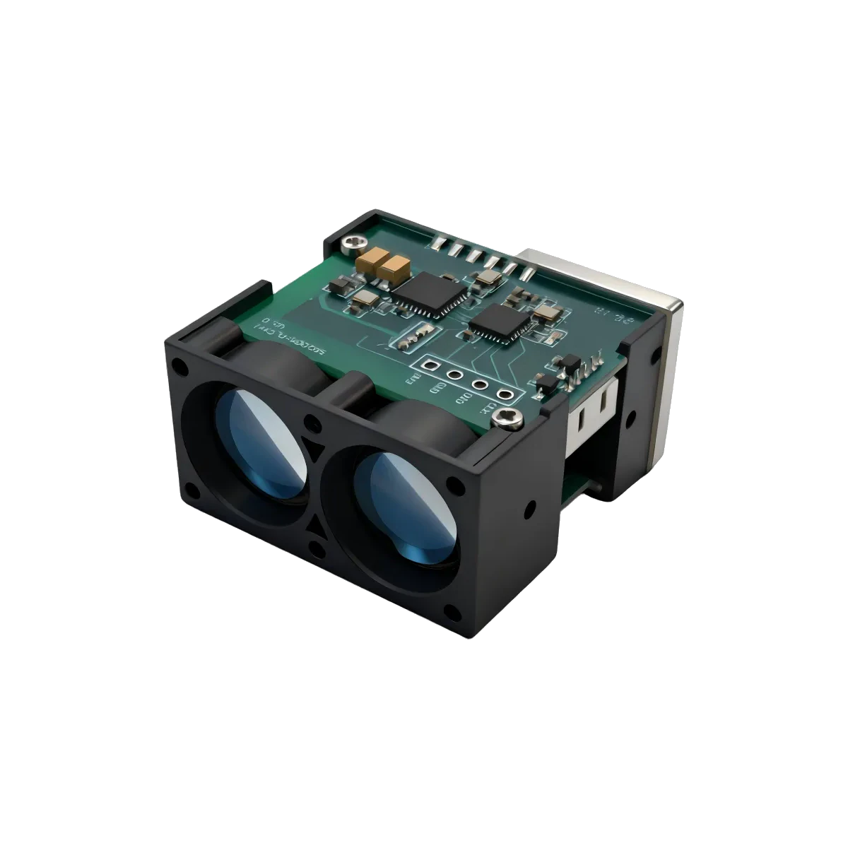
LRF100H 100 m Industrial DToF LiDAR Distance Sensor for Wind Power, Landslide and Level Monitoring
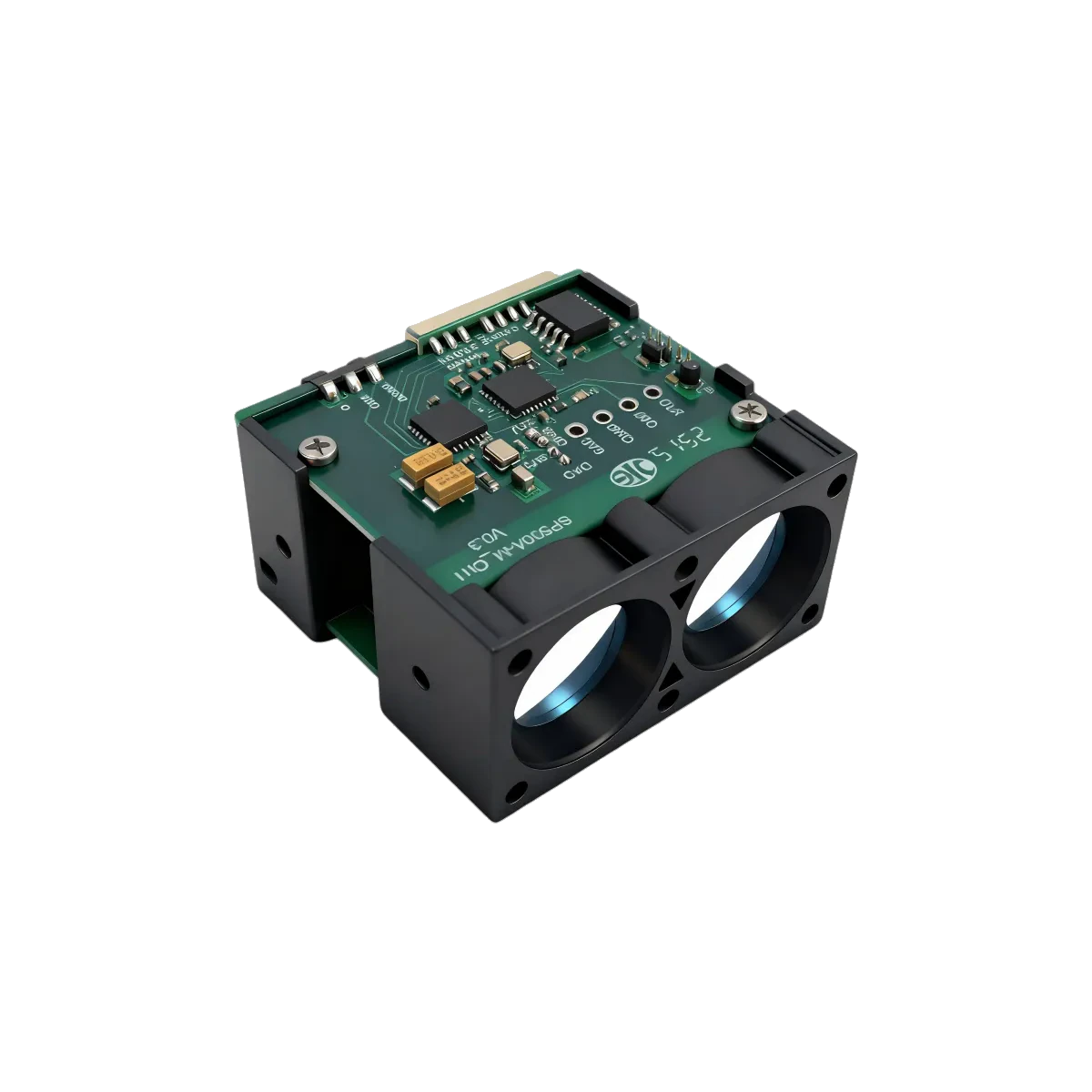
LRF300H 300 m Industrial DToF LiDAR Distance Sensor for UAV Platforms, Tower Cranes and Traffic Early Warning
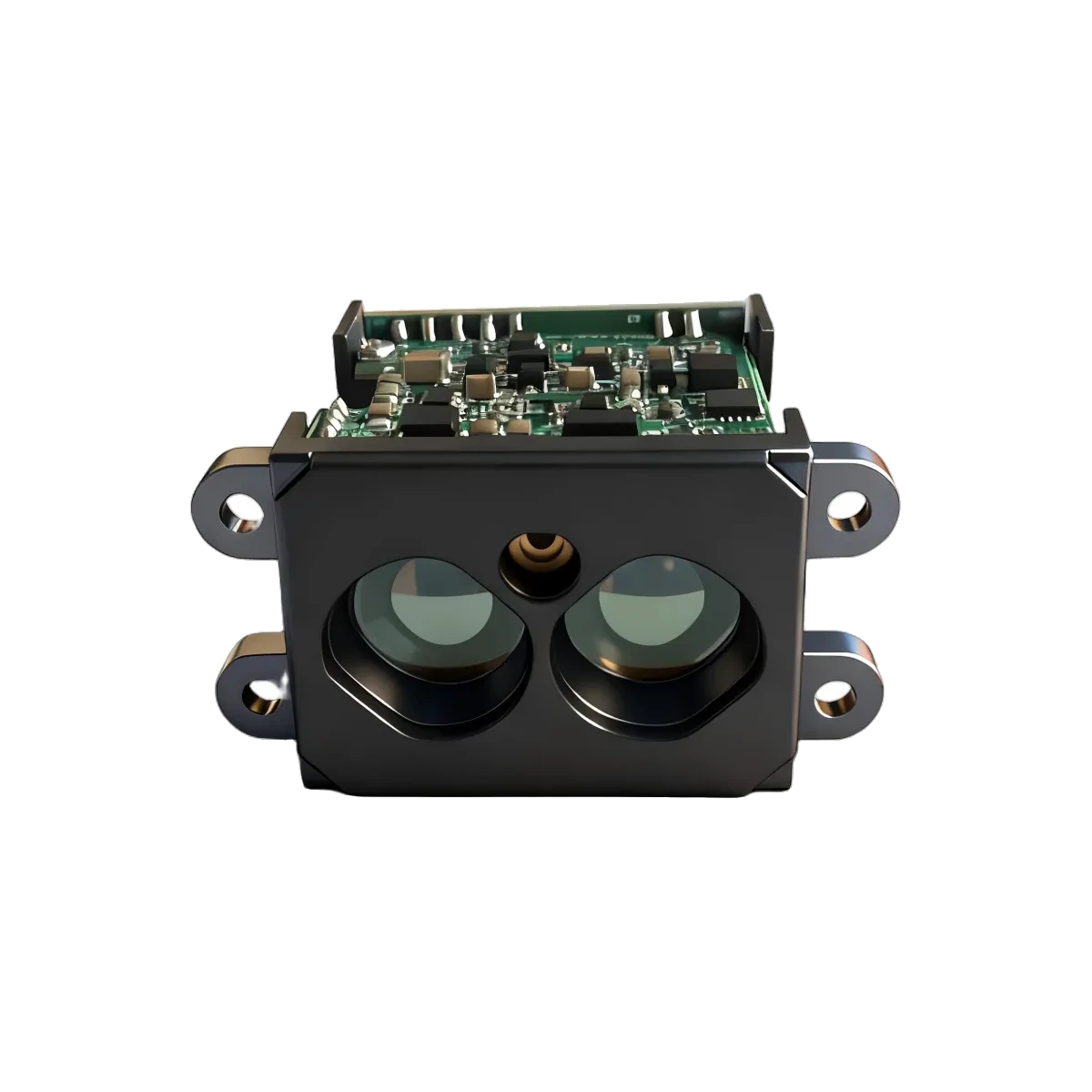
LRF50H High-Speed 50 m LiDAR Distance Sensor for Overhead Cranes, Carriage Distance Control and Industrial Safety
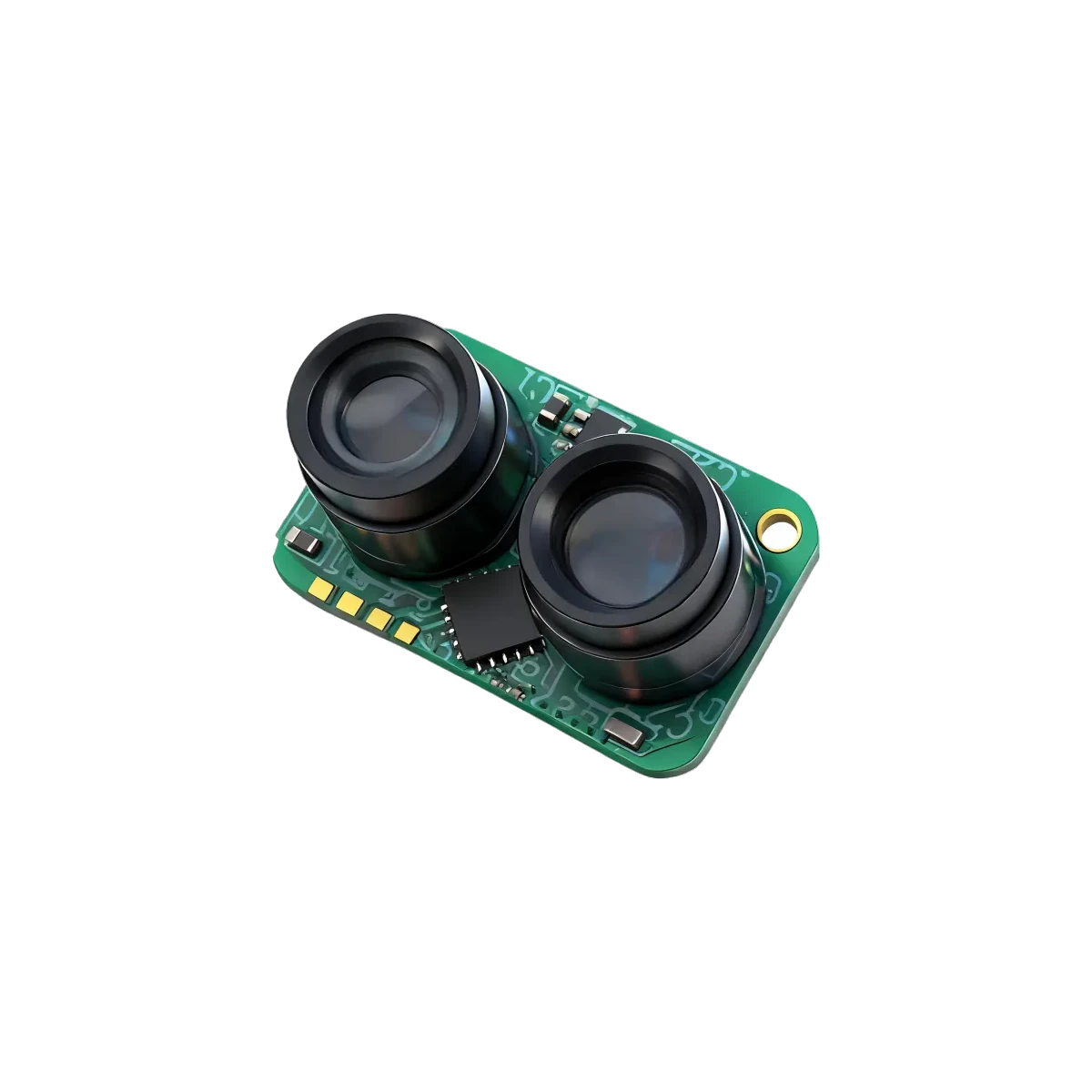
LRF50VB 50m Single-Point DToF LiDAR Sensor for Industrial Automation, AGV and Traffic Safety Monitoring
LRF22VB 20m Single-Point DToF LiDAR Sensor for Drone Altitude Hold, Robot and AGV Obstacle Avoidance