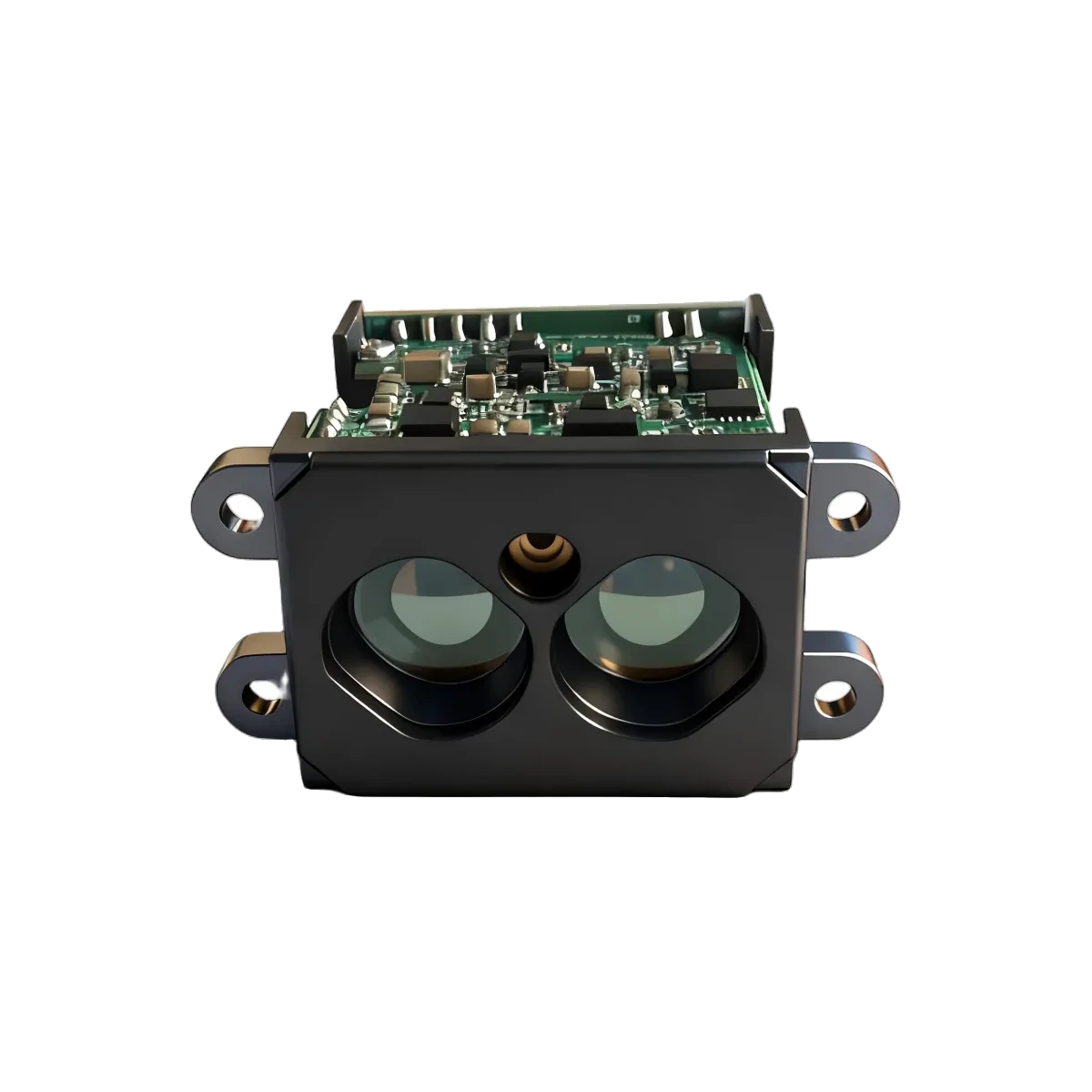
For an LRF50H aimed at a small plate, compare the documented light-spot diameter with the plate’s usable width after allowing for alignment error and movement. A plate wider than the nominal spot can still leave too little room at an edge. The calculation below turns that difference into an installation check for an industrial distance logger; it does not predict which surface the sensor will report.
Start with the documented spot, not a guessed angle
The LRF50H V3.0 documentation lists a light-spot diameter of 4 cm at 10 m and 8 cm at 20 m. Use those distance-specific entries directly for this example. The LRF50H model page provides the product context. Its documented ranging envelope is 0.05–50 m at 90% reflectivity and 0.05–15 m at 10% reflectivity. Consequently, the 20 m calculation is a geometry exercise, not evidence that a dark plate will produce a usable reading there.
Our high-rate integration guide, section 5.3, explains footprint growth and background returns. This note adds a plate-clearance budget and a controlled edge-position check. It does not infer transmitter divergence from a field-of-view label.
Calculate the remaining edge margin
For a flat rectangular plate approximately perpendicular to the measurement axis, define W as its usable width, d as the documented spot diameter at that distance, and e as a bound on the spot-centre displacement from the plate centre. In a simplified circular-footprint model, the remaining margin to the nearer side is:
M = W/2 − d/2 − e.
Use the same units for all three inputs. If a static alignment allowance a and a movement allowance b can act toward the same edge, budget e = a + b. This is a worst-case sum of bounds, not a statistical combination. If either bound is unknown, the installation margin is unknown too. Repeat the calculation with plate height and vertical displacement; passing the horizontal check alone is insufficient.
The following inputs are illustrative fixture choices, not module specifications: W = 120 mm, a = 20 mm, and b = 15 mm, giving e = 35 mm. The only product inputs are the two documented spot diameters, converted using 1 cm = 10 mm.
| Distance | Documented d | Centred clearance (W − d)/2 | Margin after e = 35 mm |
|---|---|---|---|
| 10 m | 40 mm | 40 mm | +5 mm |
| 20 m | 80 mm | 20 mm | −15 mm |
At 20 m, M = 60 − 40 − 35 = −15 mm: the nominal footprint extends beyond the usable plate boundary in this model. At 10 m, the +5 mm result leaves little geometric reserve. Neither result is a ranging pass or fail. For a chosen geometric reserve g, rearrange the same equation as W ≥ d + 2e + 2g. With an illustrative g = 15 mm at 20 m, W must be at least 80 + 70 + 30 = 180 mm. That is a fixture-planning result, not an ERDILRF minimum target-size specification.
A beam diameter is not a hard border
Edmund Optics’ official Gaussian Beam Propagation application note defines a Gaussian radius at the point where irradiance falls to 1/e² of the central value. Light is not zero outside that radius. This illustrates why a diameter definition matters; it does not establish that LRF50H has that profile or uses that convention.
The cited LRF50H spot table does not define an intensity threshold, diameter tolerance, or receiver acceptance footprint. Treat the table as a nominal planning input. The calculation also omits plate tilt, irregular beam shape and intervening optics. A positive M therefore does not prove that background light is excluded or that the intended plate will always determine the reported distance.
Check the installed geometry in five steps
- Record the scene. Note working distance, usable plate width and height, surface finish, illumination, and the position of surrounding surfaces. Do not assign a reflectivity percentage from appearance alone.
- Establish the centre and movement bounds. Document how the ranging axis is located on the plate. Measure or otherwise justify alignment and movement allowances in both directions. Include bracket drift or plate motion if they occur in service.
- Calculate both margins. Use a documented spot entry at the intended distance. For other distances, obtain suitable optical data or explicitly label any interpolation as an estimate. If M is negative or unknown, revise or characterize the geometry before relying on it.
- Exercise the edges and corners. With the sensor stationary, move the plate through the planned displacement bounds, including combinations at the corners. Keep the background representative of the installation. Save raw distances, validity information and fixture position instead of looking only at a smoothed display.
- Separate geometry from performance evidence. Compare centred and displaced records against independently known plate and background distances. Investigate unexpected returns without assuming a particular internal selection algorithm. Define acceptable errors and missing-reading limits for the application before evaluating the records.
These are proposed checks, not tests performed by ERDILRF. For help reviewing the documented inputs, contact ERDILRF with the working distance, plate dimensions and a sketch of nearby surfaces.