Application evaluation
Optical observation
5 grams of ranging, beside the intensifier tube.
The ranging module never touches your optical path.
A night-vision monocular or a thermal clip-on has already spent most of its mass and volume budget before ranging is even discussed — on the image intensifier tube or the microbolometer array, the objective, and the sealed housing that keeps both alive outdoors. Adding distance means fitting a complete direct-time-of-flight system into what is left: emitter, receive optics, avalanche photodiode, timing electronics.
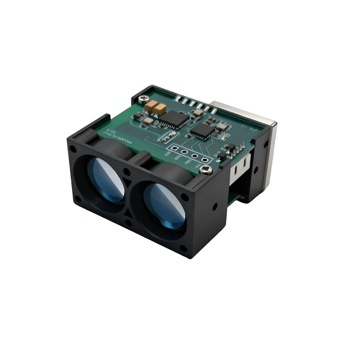
SPD1200N0 is built for that leftover volume. It is a Ø15.7 × 21.3 mm cylinder with a sealing groove, weighing about 5 grams, and it is not a cut-down part: it has a catalog range of 0.2–1,200 m and measures to ±0.3 m below 100 m and ±0.3 m + d·0.7‰ from 100 to 1,200 m. Supply is 3.3–5 V, average draw about 0.45 W with a maximum of 0.75 W, start-up ≤ 200 ms.
The integration argument that matters here is what the module does not ask of you. It does not sit in the imaging chain. It does not share a lens stack, a boresight adjustment or a coating specification with the intensifier tube or the bolometer. It mounts beside or behind the objective, roughly co-axial with the sight’s optical axis, and reports distance independently over its own UART-TTL line at 115200 bps. Your host MCU reads the frame and decides what to do with the number — render it on the display, or feed it into a reticle or ballistic calculation. The ranging module’s job ends at handing over a validated reading.
That independence is also mechanical freedom: the aperture needs an unobstructed, roughly co-axial view out of the front of the device, and beyond that the designer can put the module beside the objective, above it, or in the same housing wall as the battery compartment.
Field duty cycle is the other half. The lens cavity is IP67 — the cavity, not your finished enclosure — operating range is −20 to +60 °C with storage to −30/+70 °C, shock is rated 1000 g/ms at 10 events per second along the optical axis, vibration 5–50–5 Hz at 2.5 g, and reliability is stated as MTBF ≥ 1,500 h. Optics are PMMA with a Ø6.5 mm receiving aperture and < 4.5 mrad divergence, and the valid measurement rate is ≥ 98% with a false-alarm rate ≤ 1% under the reference conditions.
On the laser class: SPD1200N0’s field reads IEC Class 1, declared in the model manual rather than certified by a laboratory. For a device an operator points at people and animals in low light, that distinction belongs in your compliance file, not in a marketing line — and it is why we never write “eye-safe” about a 905 nm product.
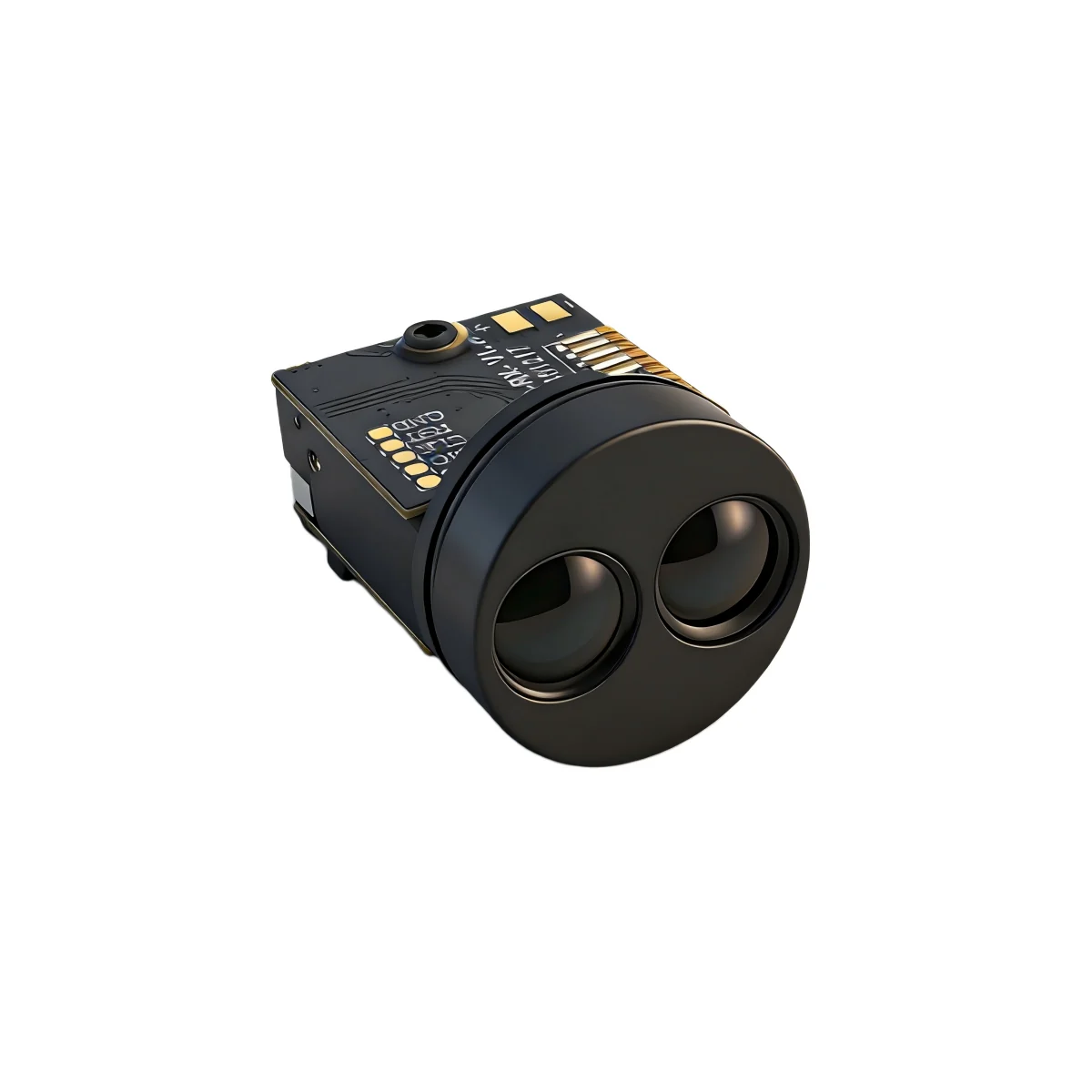
What a monocular housing has to absorb: Ø15.7 × 21.3 mm.
Bring the measurement conditions and integration constraints into the same review.
01Fitting the cavity you actually have+
Send the free cavity dimensions and the range you need. SPD1200N0’s Ø15.7 × 21.3 mm cylinder and ≈ 5 g is the smallest envelope in the 1,200 m class in this catalog; if the housing has more room, the trade is toward longer reach rather than better accuracy.
02Reading the accuracy line, not the headline+
±0.3 m holds to 100 m; past that it opens as ±0.3 m + d·0.7‰, so at 1,200 m the budget is roughly ±1.1 m. Compute it at your longest working distance before you size the readout resolution.
03The night figure is a separate figure+
1,200 m is the catalog range. The source also gives a 1,500 m figure at night, but only under special conditions, and it is not a guaranteed range. Specify your device against 1,200 m, and tell us if your application depends on night-time performance.
From the module to the host.
SPD series · UART-TTL
UART-TTL at 115200 bps, straight into your host MCU.
Check the supply, signal levels, pinout and output format for the exact model and revision. Request any missing detail before connecting your hardware.
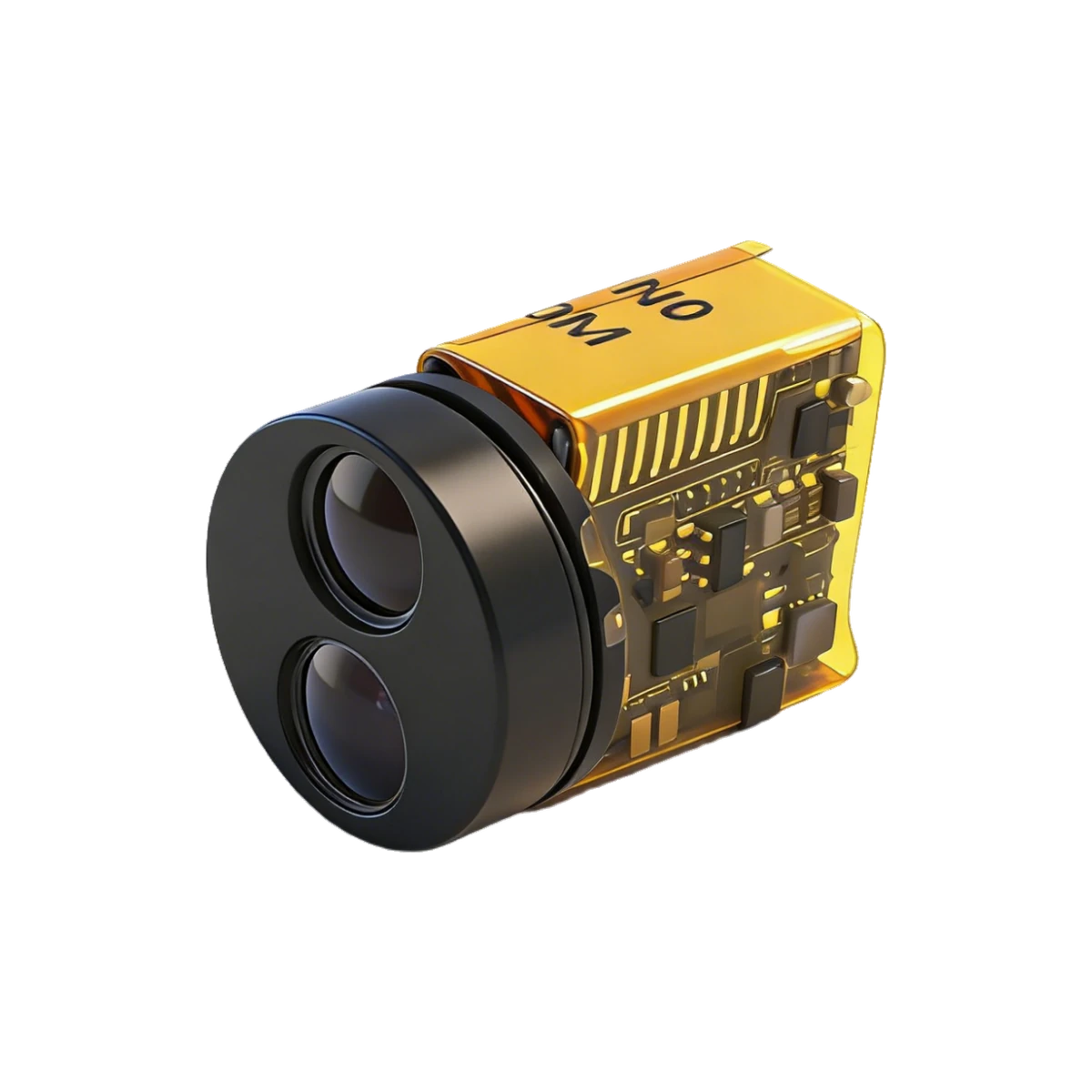 SPD1200N0
Related application pages
Share the model and distance for a technical review.
Share the distance, object surface, interface, space constraints and quantity. Include a model number if you already have one in mind.
Handheld instruments: same catalog, larger envelope, 0.1 m display resolution · Laser rangefinders in night vision and thermal devices: the long version of this page · What Class 1 does and does not cover
Confirm the current datasheet and laser safety documentation for the specific model and revision. Final suitability depends on your complete device and its operating conditions.