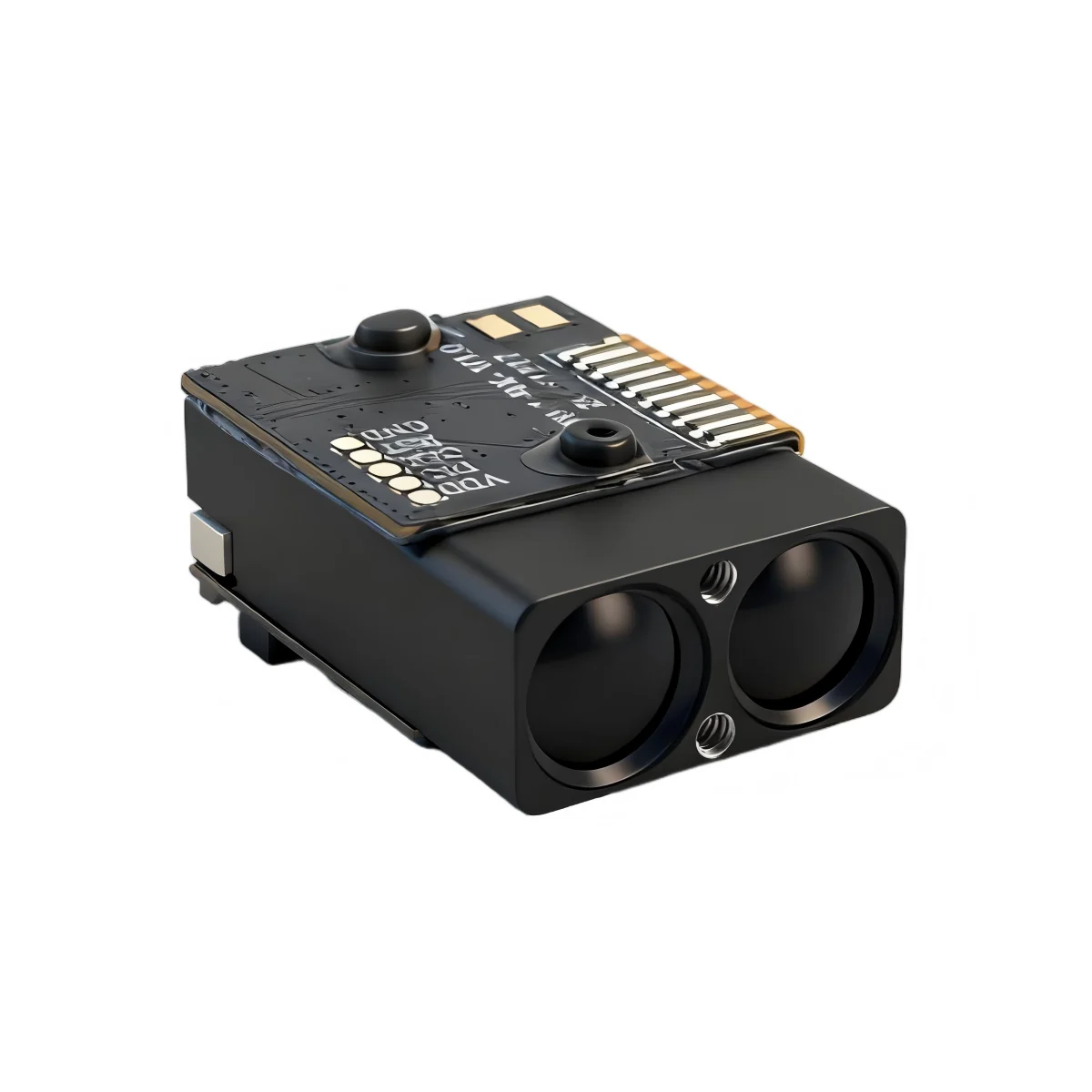
A triangulation sensor and a direct time-of-flight (dToF) module can both report a distance to the same wall. They fail for different reasons. The useful question is not which principle looks better on a datasheet; it is which one survives your target, your light, and your mounting space.
Two different ways to turn light into a number
A triangulation sensor projects a spot and images it from a second position. The baseline between emitter and receiver gives a triangle. The receiver calculates distance from the spot’s position on the image sensor. As the target moves farther away, the spot moves less for the same change in distance. Accuracy therefore falls with range, and the baseline sets a practical limit.
A dToF module measures the flight time of short light pulses, or the phase of a modulated signal, and converts that time into distance. The measurement does not depend on a baseline, so the optics can be small. The receiver still has to separate a weak return from ambient light, and the target’s reflectivity still affects the signal. The difference is where the difficulty sits.
| Question | Triangulation sensor | dToF module |
|---|---|---|
| Distance limit | Set by baseline, spot position and image resolution | Set by optical power, receiver sensitivity, target reflectivity and ambient light |
| Accuracy at range | Degrades as the spot displacement becomes small | Usually specified as an absolute figure plus a percentage of distance |
| Small or distant target | A tight spot and a long baseline help, but the geometry becomes difficult | A narrow beam and a suitable receiver aperture help; the spot must still land on the target |
| Ambient light | The image sensor can saturate or lose contrast | Narrowband filtering and a fast receiver help, but strong sunlight still costs signal-to-noise ratio |
| Mechanical build | Baseline and image-sensor alignment are part of the optics | Emitter and receiver can be packaged close together |
| Typical fit | Short-range consumer products, presence sensing, simple robotics | OEM distance modules, UAV altimetry, industrial sensing, longer-range instruments |
The target is part of the specification
Both principles need light back from the target. A white wall at close range is an easy target. A dark, wet, tilted or small target is not. A 4.5 mrad beam produces a spot roughly 22.5 cm across at 50 m and 45 cm across at 100 m. If the target is narrower than the spot, part of the return comes from the background. The receiver may average the two, report the stronger return, or drop the reading depending on its design.
That is why a range figure without a target condition is incomplete. ERDI’s model records keep the two conditions separate: for example, the LRF1500H publishes 0.05-1,500 m at 90% reflectivity and 0.05-300 m at 10% reflectivity. The second number is the one to test against a dark or non-cooperative surface. The first number is not a substitute.
Ambient light changes the receiver, not the geometry
Triangulation sensors lose contrast when the image sensor sees more ambient light than spot. dToF modules face a different problem: the return pulse arrives while the receiver is also seeing sunlight. A narrowband optical filter and a fast detector help, but they do not create signal that is not there. A module that publishes 100 klx immunity is telling you something about its receiver design under a stated test. It is not telling you that the same performance will hold through a dirty window at 60°C.
The window is part of the optical path. A recessed window, a tilted window, or a window with the wrong coating can send stray light into the receiver. In a triangulation design, the same window can also distort the spot image. Test the complete optical stack, not only the bare module.
Where ERDI fits
ERDI does not sell triangulation sensors. The catalogue is built around laser rangefinder modules. The SPD series uses short-range dToF for close-in work; the H series covers 0.05-1,500 m with UART or I²C; the LR1000E2 and LR1200E2 cover 4-1,000 m and 4-1,200 m in a UART-TTL module; the LRF3000A1 extends the long end to a 3,000 m target under a stated 70% reflectivity condition.
That matters for the comparison. If your problem is a 20 cm target at 3 m in indoor light, a small triangulation sensor may be the simpler choice. If the problem is a dark target at 150 m, or a 1,200 m measurement in daylight, a laser rangefinder module is the more realistic starting point. The model record, not the principle, decides whether the numbers fit.
A selection record you can defend
- Write the target: material, colour, approximate reflectivity, size at the working distance, and whether the surface is flat or tilted.
- Write the light: indoor, overcast, direct sun, or a strong illuminator near the receiver. Include the window and any protective mesh.
- Write the required output: absolute accuracy, repeatability, update rate, and the oldest measurement the control loop can accept.
- Write the host: supply, interface, cable length, connector, and the space available for the optics.
- Test the complete stack at the worst condition, not the easiest one. Record the target and light beside every result.
If those five items are clear, the principle usually selects itself. If they are not clear, a longer datasheet will not fix the ambiguity.
For a public overview of dToF sensing, see STMicroelectronics’ time-of-flight sensor page. For ERDI’s explanation of the 905 nm dToF measurement chain, see how 905 nm dToF laser ranging works. The model directory carries the current conditions for each module.
Send the target, light, range and host details to https://erdilrf.com/contact/. We will reply with the model records that fit, and with the items that still need a bench check.