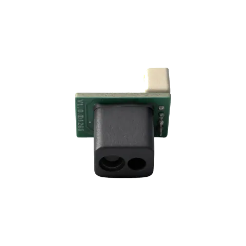
LRF10VB and LRF22VB are both Class 1 short-range time-of-flight distance modules with a 3° field of view, but their documented operating points differ sharply. LRF10VB is published at 940 nm, 0.05–9 m (90% refl.), 50 Hz and 4 mA average. LRF22VB is published at 905 nm, 0.05–20 m (90% refl.), a selectable 200 Hz and 40 mA average. The pair turns a wavelength choice into a concrete power, rate and range decision.
What the wavelength does and does not change here
Wavelength is the label most buyers reach for first, but the documented behaviour of these two modules is not indexed by wavelength. It is indexed by how much optical power the emitter must draw and how fast the receiver must decide. The 940 nm module reaches its shorter range and lower rate with a peak current of 4.5 mA; the 905 nm module reaches its longer range and selectable higher rate with a peak current of 70 mA. That single pair of numbers explains most of the rest of the differences you will see in the comparison table below: the two modules are separated far more by drive budget than by the colour of the light.
Both are listed as Class 1 in their published specifications. That statement belongs to each published model, and it should not be extended to a product family or to a whole wavelength band. If a compliance document needs a class statement, quote the model it was issued for.
Same-size pair: the documented differences
Everything below is taken from the two published model specifications. Where a specification is silent, the row says so rather than being filled in by inference.
| Documented item | 940 nm module | 905 nm module |
|---|---|---|
| Central wavelength (as published) | 940 nm | 905 nm |
| Ranging range, 90% reflectance | 0.05-9 m | 0.05-20 m |
| Ranging range, low reflectance fallback | 0.05-5 m | 0.05-10 m |
| Ranging accuracy (both listed conditions) | ±5 cm (<5 m) · 1% (≥5 m) | ±5 cm (<5 m) · 1% (≥5 m) |
| Measurement frequency | 50 Hz | 200 Hz, selectable 200/100/50/20/10/1 Hz |
| Repeatability | ±10 mm | ±30 mm |
| Ambient light immunity | 2 m | 8 m |
| Field of view | 3° | 3° |
| Peak current | 4.5 mA | 70 mA |
| Average current | 4 mA | 40 mA |
| Average power consumption | < 0.1 W (low-power mode supported) | < 0.2 W |
| Supply voltage | 4.5-5.5 V DC | 3.0-3.6 V DC |
| Interface | UART | UART / I²C |
| Dimensions | 12 × 7.5 × 9.1 mm | 21 × 15 × 7.43 mm |
| Weight | 1 g | 1.5 g |
| Out-of-range value | 65535 | 20000 |
| Laser safety class (per published spec) | Class 1 | Class 1 |
Three of these rows decide more installations than the wavelength ever does. The supply voltage windows do not overlap: 4.5-5.5 V DC on the one side, 3.0-3.6 V DC on the other. The repeatability differs by a factor of three (±10 mm against ±30 mm), which matters when you are averaging several readings to hold a tolerance. And the ambient light immunity figures — 2 m against 8 m — tell you how far the module can still work with strong light present, which is a different question from how far it can measure in dim conditions.
One row is deliberately unfinished. Neither published specification lists a UART logic level, and there is no entry for it in our field gap register. The signal-level range for the UART lines is therefore not stated here and cannot be derived from the supply voltage. Wires and pull-ups should stay disconnected until the level is confirmed from the current datasheet or from engineering, because getting this wrong is a hardware failure, not a software one.
The one hundredth-of-a-second argument
If you are comparing on wavelength alone, you are likely to miss the row that actually breaks designs: the measurement frequency. The 940 nm module has a single fixed figure, 50 Hz. The 905 nm module publishes 200 Hz and offers it as a selectable set — 200, 100, 50, 20, 10 and 1 Hz. That means the 905 nm module can be told to behave at the rate of the 940 nm module, but not the other way round.
In a moving fixture this shows up as a resolution limit, not a comfort difference. A platform travelling at 0.5 m/s covers 10 mm between readings at 50 Hz, which is exactly the repeatability figure of the 940 nm part, and 2.5 mm between readings at 200 Hz, well inside the ±30 mm repeatability of the 905 nm part. If your tolerance is a few millimetres and your carriage is not standing still, the extra rate is what buys you the measurement, not the extra range.
That is the honest way to read the pair: the 940 nm module is not a cheap substitute for the 905 nm module in a fast fixture. It is a different point on the same curve, and it wins only when the question you are answering is power and heat, not samples per second.
Where the 940 nm part actually wins
Two rows in the comparison table favour the 940 nm module outright. Average current is 4 mA against 40 mA, and average power consumption is under 0.1 W against under 0.2 W. The 940 nm specification also notes that a low-power mode is supported. When the sensor is on a coin cell, a bus-powered node, or a bank of twenty heads sharing one rail, this is the row that decides, and its own lower peak current of 4.5 mA makes the inrush far easier to fence off with a local capacitor than the 70 mA peak of the other part.
The smaller body — 12 × 7.5 × 9.1 mm and 1 g, against 21 × 15 × 7.43 mm and 1.5 g — is a secondary but real advantage when the module has to sit inside a moving head or a handset.
Note the honest counterweight: the 940 nm module’s ambient light immunity is listed at 2 m, while the 905 nm module’s is listed at 8 m. If your application must keep ranging while a strong light source is in the scene, the low-current part gives up ground there, and that is a documented trade, not an implementation detail.
Applying the choice to a real design
The 905 nm module is registered with an I²C address of 0x52 and supports a maximum bus rate of 400 kHz, so it can be read on a two-wire bus without consuming a UART port. The 940 nm module publishes a UART interface only. That difference sometimes settles the board layout before any optical question is asked.
Both modules are timestamped through the same family protocol, which is worth knowing if you are trying to run them from one firmware image. The frame header is 5C, the frame is 4 bytes, the baud rate is 460800, the distance is carried little-endian in 2 bytes, and the checksum is the sum of all bytes from the second byte to the second-last byte, inverted. Out-of-range handling is where the two part ways at the code level: the 940 nm module reports 65535, the 905 nm module reports 20000. If your parser has one sentinel constant, adding the second module silently produces a plausible-looking distance instead of an error.
Four steps will settle most real decisions faster than a datasheet read-through:
- Write down your minimum sample interval. Convert it to an equivalent rate and compare it with 50 Hz on one side and the selectable 200/100/50/20/10/1 Hz set on the other. If you need more than 50 Hz, the comparison is over — only one module can be configured to deliver it.
- Take your worst-case distance, add a safety margin, and check it against 0.05-9 m and 0.05-20 m at 90% reflectance, then against the low-reflectance fallback of 0.05-5 m and 0.05-10 m. Use the fallback row, not the headline row, when the target is dark or angled.
- Check the supply rail against 4.5-5.5 V DC and 3.0-3.6 V DC. The windows do not overlap, so this is a yes-or-no test rather than a design preference.
- Add up the average current of every head on the rail (4 mA or 40 mA each) plus the peak currents (4.5 mA or 70 mA) and confirm the local decoupling and any low-power or duty-cycle strategy can hold the rail. If the answer is tight, the low-current part earns its place even at the shorter range.
- Before wiring, confirm the UART logic level from the current datasheet or from engineering. It is not published for these modules and must not be inferred from the supply voltage.
- Confirm your out-of-range handling against 65535 and 20000, and decide whether one parser will serve both modules or each needs its own sentinel.
If more than one of those tests fails, the decision is made for you and the wavelength was never the question. If none of them fails, choose on power and heat, and let the shorter range be an accepted consequence rather than a surprise.
What you should still confirm with us
Two things are outside the published specifications and should be settled before a design freeze. First, the UART logic level, as noted above — it is not registered for either module. Second, the behaviour of the 940 nm module under your specific ambient light level: the published figure is expressed as a distance (2 m), not as a lux value, so the practical limit depends on your light source and geometry. For that specific case, the released procedure is to confirm with engineering and then reply with the actual configuration rather than with a number taken from a different test.
For earlier context on this wavelength pair, the article on 905 nm versus 1535 nm covers the long-range end of the same question, and the note on minimum measuring distance covers the near end that both modules share. The model comparison pages carry the full parameter sheets if you want to check any row above against its source. For terminology used in this article, NIST Technical Note 1297 is a public official reference for stating values with their applicable conditions; its publication record is available at https://www.nist.gov/pml/nist-technical-note-1297.
If your fixture has a fixed power budget and a fixed tolerance, send us the two numbers and we will tell you which of the two can meet both. Start at https://erdilrf.com/contact/.
Category pages: ToF distance sensor · Laser rangefinder module
Models mentioned in this article
- LRF10VB940 nm · up to 9 m · UART · 1 gFrom $9 · shipping includedSee price & buy
- LRF22VB905 nm · up to 20 m · UART · I2C · 1.5 gFrom $10 · shipping includedSee price & buy